The Reliability Block Diagram (RBD) is a graphical representation of the components of a system and the way they are interconnected. It is used to model the reliability of a system and to calculate its reliability. It’s an inductive model where a system is divided into blocks that represent distinct elements such as components or subsystems. Every element in the RBD has its own reliability (previously calculated or modelled). Blocks are then combined together to model all the possible success paths. The model topology can be different from the actual system topology.
It’s an approach to compute the reliability of a system starting from the reliability of its components. The components can be in series or in parallel.
Components in Series
Formula
Series: System failure is determined by the failure of the first component.
The RBD is composed of components with a reliability having an exponential distribution, the series system has a behavior of type exponential with a failure rate given by the sum of the failure rates of the components.
In the case of identical components, the reliability of the system in series is given by:
From the availability point of view, the availability of a system in series is given by:
and in the case of identical components:
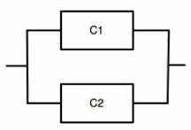
Components in Parallel
Formula
Parallel: System fails when the last component fails.
From the availability point of view, the availability of a system in parallel is given by:
RBD for a RAID-0 storage system
We have a RAID-0 storage system composed of 8 parallel disks; each disk of the system may fail independently of the others. If the reliability of each disk is
, the overall reliability of the storage system is given by:
Other Redundancy Schemes
The RBD can be used to model different redundancy schemes, such as:
-
r out of n redundancy (RooN): a system composed of
identical replicas where at least replicas have to work fine for the entire system to work fine. The reliability of the system is given by: where
is the component reliability, is the voter reliability, is the number of components, and is the minimum number of components which must survive. 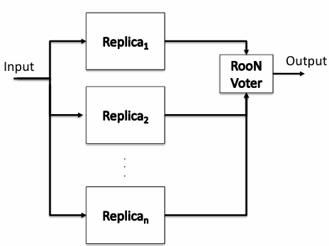
-
Triple Modular Redundancy (TMR)
-
Standby redundancy
Triple Modular Redundancy (TMR)
Definition
TMR is a redundancy scheme where the system works properly if 2 out of 3 components work properly and the voter works properly.
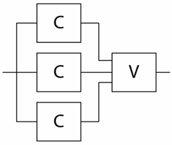
The reliability of TMR is given by:
while the mean time to failure (MTTF) of a TMR system is given by:
The
Standby Redundancy
Definition
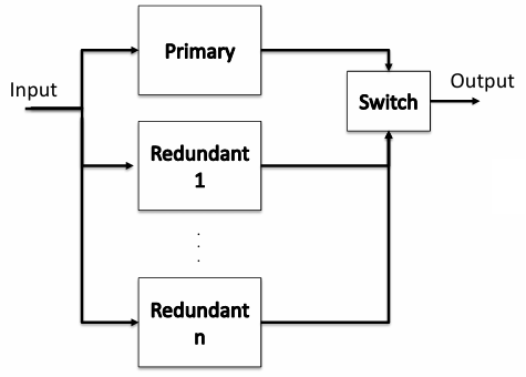
A system may be composed of two parallel replicas: the primary replica working all time, and the redundant replica (generally disabled) that is activated when the primary replica fails.
We must have a mechanism to determine whether the primary replica has failed and a dynamic mechanism to switch to the redundant replica. In general, a system having one primary and
redundant replicas, has a reliability given by: