Use Case Example: Reporting an Emergency
The “Report Emergency” use case involves two primary actors: the Field Officer and the Dispatcher. The Field Officer is responsible for reporting emergencies from the field, while the Dispatcher coordinates the emergency response. The use case begins under the entry condition that the system, referred to as FRIEND, is always available. This ensures that the Field Officer can report emergencies at any time, without restrictions on system availability.
The sequence of events starts with the Field Officer activating the “Report Emergency” function on her terminal. In response, FRIEND presents the Field Officer with a form to fill out. This form is designed to capture all relevant information regarding the emergency, including the level of the emergency (e.g., low, medium, high), the type of emergency (e.g., medical, fire, crime), the precise location, and a brief description of the situation. Additionally, the Field Officer can suggest possible responses to the emergency, providing further context for the Dispatcher. Once all the required fields are completed, the Field Officer submits the form to the system.
Upon submission, the Dispatcher is immediately notified of the new emergency report. The Dispatcher reviews the information provided to assess the situation. They then invoke the Allocate Resources use case to assign the appropriate resources to handle the emergency. This could involve dispatching medical teams, police units, or fire services depending on the nature of the emergency. After selecting a suitable response plan, the Dispatcher acknowledges the emergency report, sending a confirmation back to the Field Officer, ensuring the communication loop is complete.
The use case concludes when the Field Officer receives this acknowledgment from the Dispatcher. This acknowledgment confirms that the report has been successfully received and that a response is being mobilized. The process ends under the exit condition that the Field Officer has been informed and the emergency response is in progress.
Several exceptions can occur during this use case. For instance, if the connection between the Field Officer’s terminal and the control room is lost, the system immediately notifies the Field Officer to ensure no time is wasted. Similarly, if the connection between any logged-in Field Officer and the control room is lost, the Dispatcher receives a notification to take action. These exceptions help maintain the integrity of the reporting process, even when technical issues arise.
There are also special requirements that the system must meet. First, the Field Officer’s emergency report must be acknowledged within 30 seconds of submission. This ensures prompt communication between the actors. Secondly, the selected response must be dispatched and communicated back to the Field Officer within another 30 seconds after the Dispatcher initiates the response. These time constraints are essential to ensure that the system operates efficiently and delivers timely support in critical situations.
When formulating use cases, it is essential to follow a structured approach to ensure clarity and completeness. Here’s how the steps are applied using the Report Emergency use case:
Steps when Formulating Use Cases
Name the Use Case: The first step is to give the use case a clear and descriptive name, allowing anyone who reads it to immediately understand what it involves.
Identify the Actors: Next, identify all the actors participating in the use case. Generalize specific individuals or systems to their roles within the use case. For instance, instead of using a specific name like “Bob,” use a generalized term like “Field Officer” or “Dispatcher.” This step ensures that the focus is on roles rather than individuals.
Describe the Flow of Events, Entry, and Exit Conditions: This step involves outlining the typical flow of events in natural language. It should explain how the use case starts (entry condition), what happens during the process (flow of events), and how it ends (exit condition).
Entry Condition: When this use case starts, the system is available, and a Field Officer needs to report an emergency.
Flow of Events: The Field Officer initiates the “Report Emergency” function on her terminal. The system, FRIEND, presents a form to be filled in with details like the emergency level, type, location, and a brief description. The Field Officer fills out the form and submits it. The Dispatcher is notified, reviews the report, allocates resources, and sends an acknowledgment back to the Field Officer.
Exit Condition: The use case ends when the Field Officer receives the acknowledgment from the Dispatcher.
- Focus on Exceptional Cases and Special Requirements: Identify situations where the process might not go as planned (exceptions) and outline any specific requirements that need to be met (special requirements).
- Exceptions: If the connection between the Field Officer’s terminal and the control room is lost, the system immediately notifies the Field Officer. Similarly, if the Dispatcher loses connection with a logged-in Field Officer, they are notified.
- Special Requirements: FRIEND must acknowledge the emergency report within 30 seconds and ensure that the response is dispatched within an additional 30 seconds.
| Description | |
|---|---|
| Name | ReportEmergency |
| Actors | Field Officer, Dispatcher |
| Entry condition | When this use case starts, the system is operational, and a Field Officer is ready to report an emergency. |
| Flow of Events | The Field Officer activates the Report Emergency function on her terminal. FRIEND presents a form for the emergency report. The Field Officer fills out the details (emergency level, type, location, description, possible response) and submits the form. The Dispatcher receives the report, reviews it, allocates resources, and sends an acknowledgment back to the Field Officer. |
| Exit condition | This use case terminates when the Field Officer receives the acknowledgment from the Dispatcher, confirming the emergency report. |
| Exceptions | If the connection between the Field Officer and the control room is lost, an immediate notification is sent. The same happens if the Dispatcher loses connection with a Field Officer. |
| Special Requirements | FRIEND must acknowledge the report within 30 seconds and dispatch the response within 30 seconds after acknowledgment. |
The process outlined above can generate one or more requirements for the system. For instance:
- Requirement: FRIEND shall support Field Officers in reporting emergencies.
- Requirement: FRIEND must have a response time lower than 30 seconds when reacting to emergency-related requests.
- Requirement: FRIEND shall support Dispatchers in allocating resources to incidents.
These requirements can lead to additional, more detailed use cases that describe how the system fulfills each requirement. Each use case may lead to one or more requirements. Examples from ReportEmergency and AllocateResources:
- FRIEND shall support FieldOfficers in reporting an emergency;
- FRIEND must have a response time lower than 30 seconds when reacting to emergency-related requests;
- FRIEND shall support Dispatchers in allocating the resources to the incident.
In turn, from the requirements, new, more detailed use cases could be derived describing how the requirements are fulfilled.
Examples of Scenarios and Use Cases
Scenario on Scheduling Appointments
Example
Luigi receives a phone call from his boss informing him about a meeting scheduled for the following day from 1:00 PM to 3:00 PM. His current schedule for that day includes the following events:
- 8:00 AM - 12:30 PM: Working on the project (FixedTimeEvent: Working Event) (held at home).
- 1:30 PM - 2:30 PM: Lunch time (FlexibleTimeEvent: Personal Event, minimum length: 30 min) (held anywhere).
To manage this new event, Luigi opens his mobile application, logs in, and proceeds to insert the meeting details from the homepage. He selects the event type as “working” and then chooses “meeting” from the provided list. He adds a brief description, “Meeting with Boss,” and sets the start time to 1:00 PM and the end time to 3:00 PM. The starting location is set to “home,” and the meeting location is designated as “Harrison Street.”
The system calculates potential paths from home to Harrison Street and verifies that Luigi has enough time to arrive punctually. However, since lunch overlaps with the meeting time, the system issues a warning stating: “Lunch time overlaps with Meeting with Boss.”
| Description | |
|---|---|
| Name | Insert Fixed Time Event |
| Actor | User, GPS Service |
| Entry condition | The User knows everything about the meeting he wants to plan |
| Flow of Events | 1. In the homepage, the User clicks on the “New Event” button entering in the event creation page. 2. The User selects the type of event, by choosing it in a tree-like structured list, deciding to select as a top level of hierarchy, a working, personal or customized event. 3. The User gives a brief description of what the event will be about. 4. The User inserts the starting time, up to minutes precision, from a list box in order to avoid time not in the interval [00:00 - 23:59]. 5. The User inserts the ending time with the same procedure as the previous one, leaving the “flexible option” unchecked since he wants to insert a fixed time event. 6. The User inserts the starting position by giving the address or sharing the current position with the system using GPS technology. 7. The User inserts the position in which the event will take place. 8. The User clicks on the “Confirm” button 9. Included use case: Calculate travel paths 10. The system places the event in the calendar together with the information about how to reach it from the starting location |
| Exit condition | The event is in the User timetable. If there are overlaps with other events, warnings will be shown |
| Exceptions | The system identifies an overlap with an event that is already in the calendar (in computing overlaps the system takes into account also the time needed to move from one location to the other) and shows them as warnings to the User offering the possibility to modify the schedule. User cannot find the event type he is looking for. In this case, the User is able to insert a new type of event, exploiting the “Insert new type of event” functionality and then back to step one on the flow of event |
| Special Requirements | The daily timetable must be updated in less than 1 second |
In this example, we can identify several phenomena that occur in the world and are controlled by the user, the system, or both. These phenomena can be categorized as follows:
| Category | Phenomena |
|---|---|
| World-only phenomena | User sets up meeting; User goes to meeting |
| Shared phenomena, world-controlled | User inserts time of meeting; User inserts place of meeting; User selects type of event; User confirms meeting |
| Shared phenomena, machine-controlled | System warns user of overlap between events |
| Machine-only phenomena | System computes path; System stores event |
In this scenario, we can identify some goals and domain assumptions that help define the system’s requirements:
- Goals:
: Users keep track of events in which they are involved; : Users avoid scheduling overlapping
- Domain Assumptions:
: The information about events inserted by users is correct; : GPS data is accurate (error of 20m at most)
- Requirements:
: The system shall allow the user to create a new event; : The system shall allow the user to set the time of the event; : The system shall allow the user to select the type of the event; : The system shall allow the user to set the place of the event; : When user confirms an event, the system shall update the timetable in less than 1s

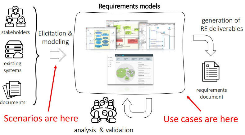
The graph presents a structured view of the relationship between use cases, requirements, and various external factors in system development. It begins with the concept of Nature, which encompasses three primary elements: People, Infrastructure, and Documentation. These components represent the real-world entities that influence the system. People are the users or stakeholders who interact with the system, infrastructure refers to the technological or physical components required to support it, and documentation provides the necessary information and guidelines. Together, these three elements shape how the system operates and interacts with its environment.
Scenarios play a central role in the graph, connecting directly to Nature. Scenarios are real or hypothetical situations that illustrate how the system should function in various conditions, driven by the influence of people, infrastructure, and documentation. Scenarios are also closely tied to Requirements Models (RM), showing that they inform the development of these models, while simultaneously being influenced by them. This relationship emphasizes the importance of understanding real-world situations when designing the system’s requirements and goals.
At the heart of the graph is the Requirements Models section, which shows a cyclic relationship between Goals, Use Cases, Domain Assumptions, and Requirements. Goals represent the high-level objectives the system must achieve, while Use Cases describe the specific actions required to meet those goals. Domain Assumptions are the underlying conditions considered true within the system’s context, and Requirements outline the system’s functionalities based on these assumptions. The cyclic structure indicates a continuous interaction between these elements, where goals drive use cases, use cases are shaped by assumptions, and both feed into the formulation of requirements, which in turn refine the goals.
Finally, Phenomena are linked to Nature and connect with the Requirements Models. These represent observable events or behaviors in the real world that affect or are captured by the system. They influence the requirements, goals, and use cases by providing concrete instances of how the system interacts with its environment. In this way, the graph as a whole illustrates the intricate web of relationships between the real world (people, infrastructure, and documentation), abstract models (scenarios, phenomena), and the formal structures of system development (goals, use cases, and requirements).