graph LR
    subgraph "Static Modelling"
        US[Use Cases]
        CL[Class<br>Diagrams]
        OB[Object<br>Diagrams]
        CD[Component<br>Diagrams]
        DD[Deployment<br>Diagrams]
    end

    subgraph "Dynamic Modelling"
        AD[Activity<br>Diagrams]
        SM[State Machine<br>Diagrams]
        CCD[Collaboration<br>Diagrams]
        SD[Sequence<br>Diagrams]
    end
    M[(Models)]

    US --- M
    CL --- M
    OB --- M
    CD --- M
    DD --- M

    M --- AD
    M --- SM
    M --- CCD
    M --- SD
Use Cases and UML
Use cases are essential tools in understanding the interactions within a system, particularly concerning the flow of events that occur between the system and its users, referred to as actors. Each use case begins with an actor’s initiation and concludes when specific conditions are met, thus demonstrating a complete cycle of interaction. Every use case is assigned a unique name and contributes to a broader framework known as the use case model. This model encompasses all the use cases related to the system, effectively capturing its complete functionality. By providing a structured representation of user interactions, use cases facilitate communication among stakeholders, ensuring a shared understanding of system requirements and functionalities.
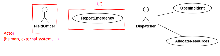
The Unified Modeling Language (UML) provides a visual representation of use cases, allowing developers and analysts to depict the relationships and interactions in a clear and concise manner. A UML use case diagram is particularly beneficial as it illustrates not only the various use cases but also the actors involved and their relationships. This representation aids in visualizing how different parts of the system interact, making it easier to identify the roles that users and other systems play in achieving the overall goals of the software.
| Generalization | Extend | Include |
|---|---|---|
| Base use case could be abstract use case (incomplete) or concrete (complete) | Base use case is complete (concrete) by itself, defined independently | Base use case is incomplete (abstract use case) |
| Specialized use case is required, not optional, if base use case is abstract | Extending use case is optional, supplementary | Included use case is required, not optional |
| No explicit location to use specialization | Has at least one explicit extention location | No explicit inclusion location but is included at some location |
| No explicit condition to use specialization | Could have optional extension condition | No explicit inclusion condition |
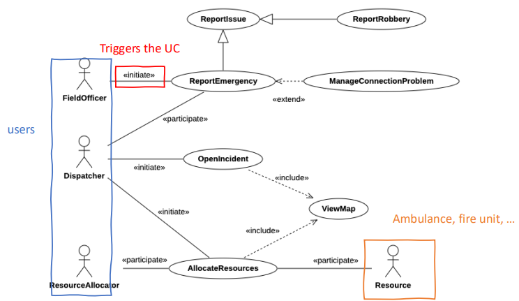
Within the framework of use cases, associations describe the relationships that exist between different use cases. Three significant types of associations are include, extend, and generalization. The <<include>> association occurs when one use case incorporates the functionality of another use case, facilitating functional decomposition. This means that the included use case is necessary for the execution of the base use case, ensuring that essential operations are clearly defined and reusable.
In contrast, the <<extend>> association denotes a situation where a use case can add additional behavior to another use case under certain conditions. The extending use case is considered optional and serves to provide supplementary functionality, enhancing the base use case without altering its core behavior.
Example
For example, an e-commerce application might include a standard checkout process (base use case) that can be extended with additional options like applying discounts (extending use case) based on specific promotional conditions.
The generalization association involves an abstract base use case that can have several specialized variations. The base use case can be incomplete or concrete, while the specialized use cases inherit attributes and behaviors from the base. Generalization allows for a hierarchical structure, promoting code reuse and simplifying the management of related use cases. The specialized use cases become necessary when the base use case is abstract, as they are required to provide the specific functionalities that fulfill user needs.
Requirements-level class diagrams
Requirements-level class diagrams are conceptual models that focus on the high-level structure of an application’s domain, without delving into the technical details of object-oriented software design. Unlike class diagrams used in the software design phase, which are closely tied to implementation, these diagrams are more abstract and serve to capture the key entities and their relationships within the problem domain. They are particularly useful during the early stages of development when understanding the domain’s structure and its key concepts is critical.
One distinguishing feature of requirements-level class diagrams is that they may include entities that will not necessarily be implemented in the final software system. These diagrams focus on representing concepts that are important for understanding the problem domain, which means that not all entities depicted will have a corresponding representation in the software. This abstraction helps analysts and stakeholders gain a clear understanding of the domain without being constrained by design or technical implementation considerations.
In these diagrams, the operations (or methods) of entities are usually not modeled.
The goal is to capture the relationships and attributes of entities at a high level, leaving the detailed behavior and specific functions of these entities for later phases of software development, such as detailed design.
However, in some cases, it may be useful to introduce a few high-level functions of the system to aid in understanding the overall interaction between entities. These functions provide a broad view of system behavior but remain abstract enough to avoid design-level commitments.
A critical aspect of requirements-level class diagrams is that they encourage postponing decisions regarding the specific operations and methods that will be implemented in the software. By deferring these decisions to the software design phase, developers can maintain flexibility in how the system will be built. This separation of concerns helps ensure that the analysis phase remains focused on accurately capturing the domain, while the design phase can focus on how to translate that understanding into concrete, technical solutions.
Trip tracker
Consider a system that alerts travelers about issues on their preferred routes. It monitors various transportation modes and sends notifications to users when problems are detected on their monitored routes. Notifications are only sent to users interested in those specific routes. The system handles both long-distance routes (intercity trains, flights) and urban public transport (metro, bus, trams). Each route has an identifier and a set of stops, with each stop having a name and geographical coordinates. For long-distance routes, stops also have arrival and departure times; for urban routes, each line has a consistent stop frequency (e.g., “every 5 minutes”).
The system tracks different types of problems based on the transportation mode. For long-distance routes, it monitors expected delays at stops, with notifications including the route ID, stop, nominal arrival time, and expected delay. For urban transport, it monitors interruptions or slowdowns, with notifications including the line ID, affected segment (departure and arrival stops), and problem description (slowdown or interruption).
Users can subscribe to notifications for specific routes by providing their user ID and the route ID. They can also unsubscribe by indicating their user ID and the route ID they are no longer interested in. When a problem is detected on a subscribed route, the system sends a notification to the user with the relevant problem information.

Dynamic modeling
Dynamic modeling is an essential process in understanding and depicting how a system behaves over time by focusing on interactions between participants, their behaviors, and the overall workflow within the system. Its primary objective is to capture the system’s runtime behavior and ensure that the flow of activities, use cases, and object interactions are well-understood and documented. Dynamic models provide insights into how the components of a system collaborate to achieve its goals by using diagrams that emphasize different aspects of system behavior.
To achieve this, dynamic modeling is structured around key use cases or scenarios and employs various types of diagrams to model interactions, object behaviors, and workflows. These include sequence diagrams for interaction modeling, state machine diagrams for documenting the behavior of individual objects, and activity diagrams for modeling workflows.
Sequence diagrams
A sequence diagram is a graphical representation that focuses on the interaction between objects in a use case or scenario. It uses a Directed Acyclic Graph (DAG) notation to show how messages are passed between objects over time. This diagram offers a detailed view of how objects collaborate to fulfill a particular function.
Algorithm
To construct a sequence diagram, the following steps are typically followed:
- Analyze the flow of events in a use case or scenario: Identify key actions that occur and the order in which they take place.
- Identify sender and receiver: Every event in the scenario has a sender (the object or actor initiating the event) and a receiver (the object or actor responding to it).
- Represent the event as a message: In the sequence diagram, events are represented as messages flowing between the participating objects.
- Define the participating objects: Objects that interact within the use case are identified, usually based on the earlier stages of object modeling, ensuring consistency between different views.
Objects/classes have already been identified during object modeling. Different views must be consistent. Objects may emerge from dynamic modeling.
For example, the diagram below illustrates how a user interacts with a system by subscribing to a route, and the system subsequently computes problems and sends notifications.
user: 2: | system -> system: 3: computeProblems() | system -> user: 4: notify(prob) | | end | | @enduml | -->State Machine diagrams
A state machine diagram captures the dynamic behavior of an individual object over time. These diagrams are particularly useful for modeling objects that go through a series of state changes in response to events. State machine diagrams document how an object moves from one state to another, showing the possible states and transitions that an object can experience throughout its lifecycle.
For instance, in a system like Trip Tracker, a problem object may go through several states, such as “reported,” “under investigation,” and “resolved.” The state machine diagram would depict these states and the events that trigger transitions between them.

Summary
State diagram Sequence diagram Focus on changes in an individual object over time Focus on the interaction between objects over time Class-level documentation Instance-level documentation We can infer many possible event and order-dependent behaviors Shows one specific case or a subset of cases
Activity diagrams
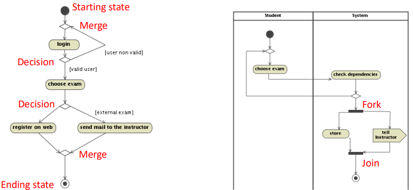
Activity diagrams model the workflow or process within a system, without focusing on specific object responsibilities. These diagrams highlight the flow of activities and how they relate to one another, emphasizing the overall process rather than object interactions. They are useful for modeling business processes or workflows, making them ideal for describing activities that involve multiple actors or systems.
For example, an activity diagram could be used to describe a "register on the web" process by identifying the responsibilities of both the student and the system.
Summary
Sequence diagram Activity diagram Focus on object interaction Focus on activities and flow of activities Suited for describing an interaction protocol Suited for describing a process
Modelling the Airbus braking logic with UML
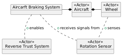
Modeling the braking logic of an Airbus aircraft using UML involves understanding the system’s core entities, their relationships, and dynamic behaviors, such as how reverse thrust is enabled when certain conditions are met. This approach provides a high-level representation of the system’s functionality but lacks the ability to fully express assertions about domain properties and requirements. As such, while UML offers a graphical overview, it must often be complemented with additional formal or informal descriptions to express critical logical assertions that UML cannot capture directly.
Main entities and relationship
In modeling the braking logic, the main entities include:
- Aircraft: Represents the Airbus aircraft, which interacts with the braking system.
- Braking Controller: Manages the aircraft’s braking system, including the application of brakes and reverse thrust.
- Wheel: Monitors the rotation of the aircraft’s wheels, detecting pulses to determine if the aircraft is moving.
- Reverse Thrust System: Engages the reverse thrust mechanism when the wheels are confirmed to be rotating.
- Rotation Sensor: Detects wheel pulses to signal that the wheels are turning.
Aircraft States
The states of the aircraft represent different phases in the aircraft’s operation, such as:
- Parked: The aircraft is stationary on the ground, with the brakes engaged.
- Moving on runway for takeoff: The aircraft is accelerating on the runway, preparing for takeoff.
- Taking off: The aircraft is lifting off the ground, transitioning to flight mode.
- Flying: The aircraft is in the air, with the landing gear retracted.
- Landing: The aircraft is descending for landing, preparing to touch down on the runway.
- Moving on runway for landing: The aircraft is decelerating on the runway, approaching the landing phase.
- Moving to the parking area: The aircraft is taxiing to the parking area after landing.
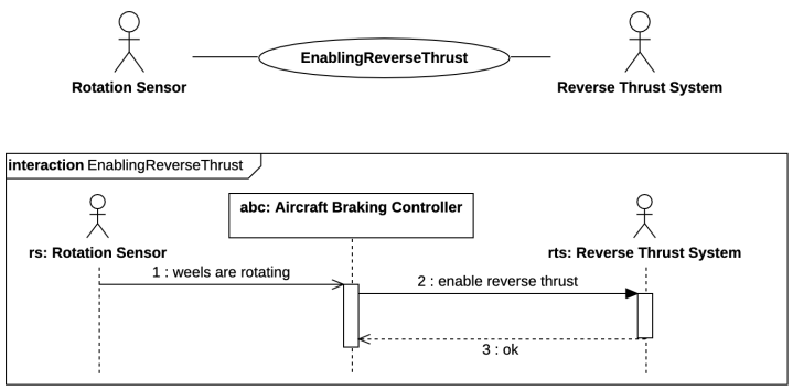
Enabling Reverse Thrust When Wheels Are Rotating
One of the critical dynamic behaviors of the braking system is that reverse thrust can only be enabled when the wheels are confirmed to be rotating. This condition ensures that reverse thrust is only applied when the aircraft is physically in contact with the runway and moving, preventing dangerous activation in the air.
The process can be modeled with sequence diagrams that illustrate the interaction between entities like the aircraft, sensors, wheels, and the reverse thrust system. The sensor detects wheel pulses, signaling that the wheels are rotating. Once this condition is met, the reverse thrust system can be engaged. If no wheel pulses are detected, reverse thrust remains disabled.
Challenges with Expressing Assertions
While UML provides a powerful framework for modeling the structural and dynamic aspects of the Airbus braking system, it does not inherently support the expression of logical assertions—critical in ensuring that the system behaves correctly in all cases. Specifically, the system includes domain properties and requirements that need to be formally described, such as:
- Goals: These represent the high-level objectives, such as:
Reverse_enabled ⇔ Moving_on_runway: Reverse thrust can only be enabled when the aircraft is moving on the runway.
- Domain Properties: These are invariant truths about the system’s environment, including:
Wheel_pulses_on ⇔ Wheels_turning: If the sensor detects pulses, the wheels are turning.Wheels_turning ⇔ Moving_on_runway: The wheels are turning only if the aircraft is moving on the runway.
- Requirements: These express the necessary conditions for the system to function correctly:
Reverse_enabled ⇔ Wheels_pulses_on: Reverse thrust can only be enabled when wheel pulses are detected.
A potential problem arises with the domain property Wheels_turning ⇔ Moving_on_runway, which might not fully capture the complexities of the system. For instance, the aircraft might be moving on the runway without wheel pulses due to slippage, or the wheels might turn without sufficient movement on the runway. This discrepancy highlights the limitation of using pure UML for expressing domain properties that involve subtle logical conditions.
Complementing UML with Assertions
To fully express such properties and requirements, UML models need to be complemented with formal or informal descriptions that articulate the precise conditions under which the system operates. This can be done through:
- Formal Methods: Such as using temporal logic or specification languages like Alloy to define domain properties and system constraints.
- Informal Descriptions: Accompanying UML diagrams with natural language explanations that clarify these properties and relationships, making sure that stakeholders understand the exact logic behind system behaviors.
For example, an assertion like Reverse_enabled ⇔ Wheels_turning can be expressed formally to ensure that the system is designed to adhere to this condition, but UML itself will not enforce or validate this. Therefore, additional documentation or formal verification techniques are necessary to ensure the system behaves as intended in all scenarios.