In the context of database systems, reliability is a critical measure of a system’s ability to function correctly and consistently over time, especially in the presence of failures.
Definition
We define the reliability as the ability of an item to perform a required function under stated conditions for a stated period of time.
In databases, reliability control is the set of mechanisms that ensures the fundamental properties of transactions are upheld, even when failures occur. These properties are primarily Atomicity and Durability from the ACID paradigm.
- Atomicity: Ensures that a transaction is an “all or nothing” operation. Either all of its effects are reflected in the database, or none are.
- Durability: Guarantees that once a transaction has been successfully committed, its effects are permanent and will survive any subsequent failures, such as a power outage or system crash.
To achieve this, Database Management Systems (DBMS) implement a specific architecture for reliability control. The two cornerstones of this architecture are stable memory and log management.
Architecture of the Reliability Manager
The Reliability Manager is a core component of the DBMS architecture responsible for ensuring transaction atomicity and durability. It coordinates with other components like the Transaction Manager, Buffer Manager, and Concurrency Control System to manage transactions and handle recovery.

The primary responsibilities of the Reliability Manager are:
- Realizing transactional commands: It handles the
commitandabortcommands issued by the Transaction Manager. - Orchestrating data access: It manages read and write access to pages in the buffer, for both database data and the transaction log.
- Handling recovery: In the event of a system failure, it is responsible for restoring the database to a consistent state.
Persistence of Memory
The concept of durability requires a form of memory whose contents can survive failures. This leads to the abstraction of different levels of memory persistence.
- Main Memory (e.g., RAM): This is not persistent. Its contents are lost during a power failure or system shutdown.
- Mass Memory (e.g., HDD, SSD): This memory is persistent, meaning its contents survive power loss. However, it can be damaged by hardware failures (e.g., a disk head crash).
- Stable Memory: This is an idealized abstraction of memory that cannot be damaged and whose contents last forever. In practice, stable memory is implemented by aiming for a probability of failure that is close to zero. The key techniques to achieve this are replication and the use of specific write protocols.
The failure of stable memory is a catastrophic event that is addressed by the discipline of disaster recovery.
How to Guarantee Stable Memory
Stable memory is practically achieved through replication strategies that protect against data loss.
-
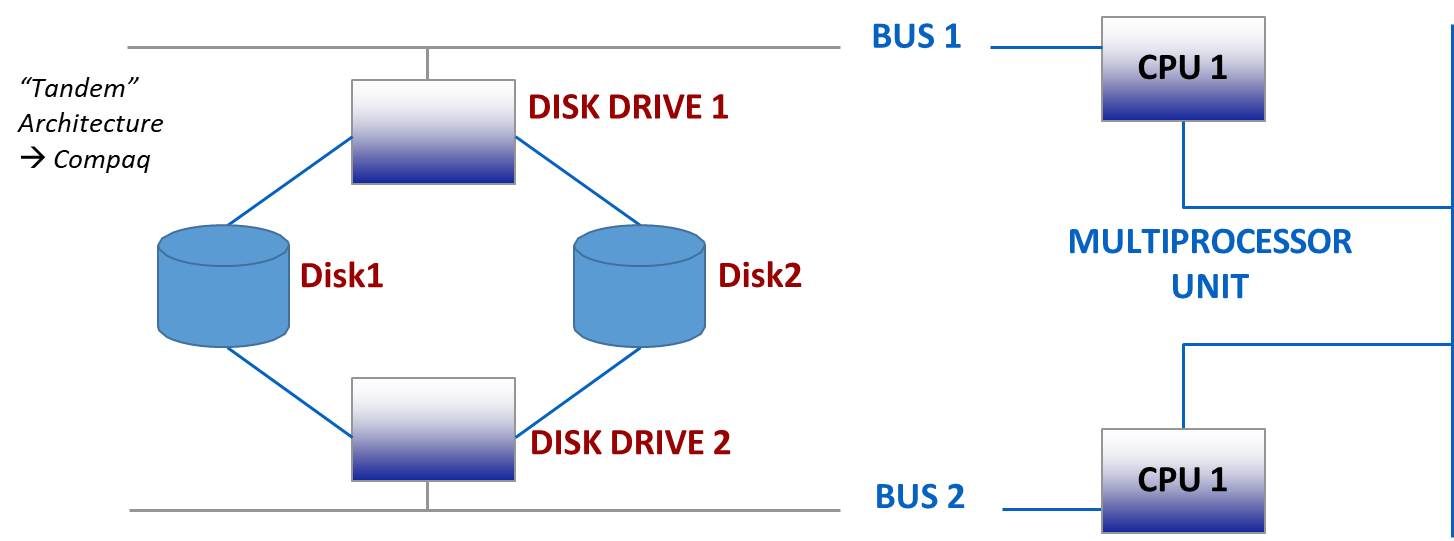
On-line Replication: This involves creating real-time, mirrored copies of data. A common implementation is RAID (Redundant Array of Independent Disks), which distributes data across multiple disks to provide fault tolerance. For example, in a mirroring setup (RAID 1), data is written to two separate disks simultaneously. If one disk fails, the other can be used for recovery.
-
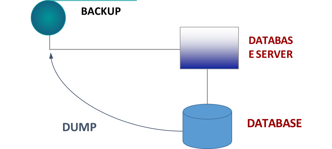
Off-line Replication: This involves creating periodic backup copies of the database. These backups, traditionally stored on “tape” units, are created by “dumping” the database content to a separate storage medium. In case of a failure of the primary and secondary storage, the database can be restored from the most recent backup.
Main Memory (Buffer) Management
A central challenge in database design is achieving a balance between stability and performance. Accessing data directly from persistent secondary storage is inherently slow. To address this, DBMSs allocate a significant portion of main memory to serve as a buffer or cache. This buffer acts as an intermediary, holding frequently accessed data in faster memory and thereby reducing data access times.
The use of a buffer enables deferred writing, where changes made to the data are temporarily stored in main memory and written to disk at a later, more optimal time. This approach not only improves performance but also allows the DBMS to group and optimize disk writes, further reducing overhead (and so, the lifespan of the storage medium).
Buffers are organized in units called pages, with each page potentially containing multiple rows of data. Every page in the buffer is accompanied by metadata that helps manage its state. Two important pieces of metadata are the transaction counter and the dirty flag. The transaction counter keeps track of how many active transactions are currently using the page, ensuring proper coordination and consistency. The dirty flag is a boolean indicator that signals whether the page has been modified in memory and is now inconsistent with its version on disk. Pages marked as dirty must eventually be written back to secondary storage to maintain data integrity.
Note
On dedicated DBMS servers, it is common for up to 80% of the total physical memory to be allocated to the buffer pool to maximize performance.
Buffer Management Primitives
The buffer manager provides a set of primitives to manage the movement of pages between disk and the buffer pool.

fix: Responds to a request from a transaction to load a page from disk into the buffer. It returns a reference to the page in the buffer and increments its usage count.unfix: De-allocates a page from a transaction’s usage, decrementing its usage count.force: Synchronously transfers a specific page from the buffer to the disk, ensuring it is immediately written.setDirty: Sets the dirty flag for a page to true, indicating it has been modified.flush: Asynchronously transfers dirty pages from the buffer to the disk. This is typically done for pages that are no longer needed (i.e., their usage count is 0).
When a transaction requests a page using fix, the buffer manager follows these steps:
Steps
- Search the buffer: It first checks if the page is already in the buffer. If so, it increments the usage counter and returns the reference.
- Find a free page: If the page is not in the buffer, it looks for a free slot (a page with
usage_counter == 0). If a free slot is found, the new page is loaded. If the slot previously held a dirty page, that page is flushed to disk first.- No free page found (Victim Selection): If there are no free pages, a replacement policy is used to select a “victim” page to evict.
- STEAL Policy: Allows the buffer manager to grab a page that is currently being used by another active transaction. This victim page is written to disk (if dirty), and the new page is loaded in its place.
- NO STEAL Policy: Prohibits taking a page from an active transaction. The requesting transaction is put on a wait list until a page becomes free.
Buffer Management Policies
The interaction between the buffer manager and the rest of the DBMS is governed by several key policies that balance performance and reliability.
-
Write Policies: These policies dictate when modified pages are written to disk.
- FORCE: All pages modified by a transaction are
forcedto disk at the time of commit. This ensures durability but can be slow. - NO FORCE: The transfer of modified pages can be delayed. The buffer manager can write pages to disk at a later, more optimal time. This improves performance but requires careful logging to ensure durability in case of a crash.
- FORCE: All pages modified by a transaction are
-
Replacement Policies: As discussed, these determine which page to evict when the buffer is full.
- STEAL: Allows evicting a dirty page from an uncommitted transaction.
- NO STEAL: Prevents evicting pages from uncommitted transactions.
-
PRE-FETCHING (Read-Ahead): The system anticipates which pages a transaction is likely to need next (e.g., in a sequential scan) and loads them into the buffer proactively. This is particularly effective for sequential reads.
-
PRE-FLUSHING: The system anticipates the writing of de-allocated pages to speed up future
fixoperations that might need the space.
Note
A common default configuration in many DBMS is NO STEAL and NO FORCE, which optimizes for performance but places a heavy reliance on the transaction log for recovery.
Failure Handling and Recovery
Definition
A transaction is an atomic transformation of the database from one consistent state to another.
Failures can interrupt this process, requiring the Reliability Manager to intervene.
When a transaction is executed, there are several possible outcomes.
- If the transaction completes successfully, it issues a
commitand its effects should become permanent. - If the transaction fails or is explicitly aborted before reaching the commit point, a
rollbackis performed and all of its effects must be completely undone—this is handled by the UNDO process.
A third scenario occurs when a system failure happens after a transaction has committed but before all its changes have been written from the buffer to disk. In this case, the Reliability Manager is responsible for ensuring that these changes are eventually applied to the database, which is accomplished through the REDO process.
These outcomes have important implications for recovery. To guarantee durability, if a failure occurs after a transaction has committed, the Reliability Manager must use the transaction log to REDO (or roll forward) the transaction’s updates, ensuring they are properly persisted on disk. To guarantee atomicity, if a transaction had not committed at the time of failure, the Reliability Manager must UNDO (or roll back) any partial effects that may have been written to disk, restoring the database to a consistent state.
The Transaction Log
The transaction log (or journal) is the cornerstone of database recovery.
Definition
The Transaction log is a sequential, append-only file stored in stable memory that contains records describing all the actions performed by transactions.
The log records state transitions, capturing the “before” and “after” images of data that is modified.
If an UPDATE before-state(U) = O1 and an after-state(U) = O2. This allows the system to recover from failures by either undoing changes (using the before-state) or reapplying them (using the after-state).
In case of an INSERT operation, the log will contain an after-state but no before-state, as there was no previous state of the object. For a DELETE, the log will contain a before-state but no after-state, as the object is removed.
The log is used to perform UNDO and REDO operations for recovery.
- UNDO: To reverse the effects of a failed or rolled-back transaction, the
BEFORE-STATEfrom the log is used to restore the original data.UNDO T1: O = O1. - REDO: To re-apply the effects of a committed transaction after a crash, the
AFTER-STATEfrom the log is used.REDO T1: O = O2.
Important
Both UNDO and REDO operations must be idempotent. This means that applying the operation multiple times has the same effect as applying it once (e.g.,
REDO(T) = REDO(REDO(T))).This is crucial because during recovery, the system may be unsure if an operation was already successfully applied before a crash, so it may attempt it again. Idempotency ensures this re-attempt does no harm.
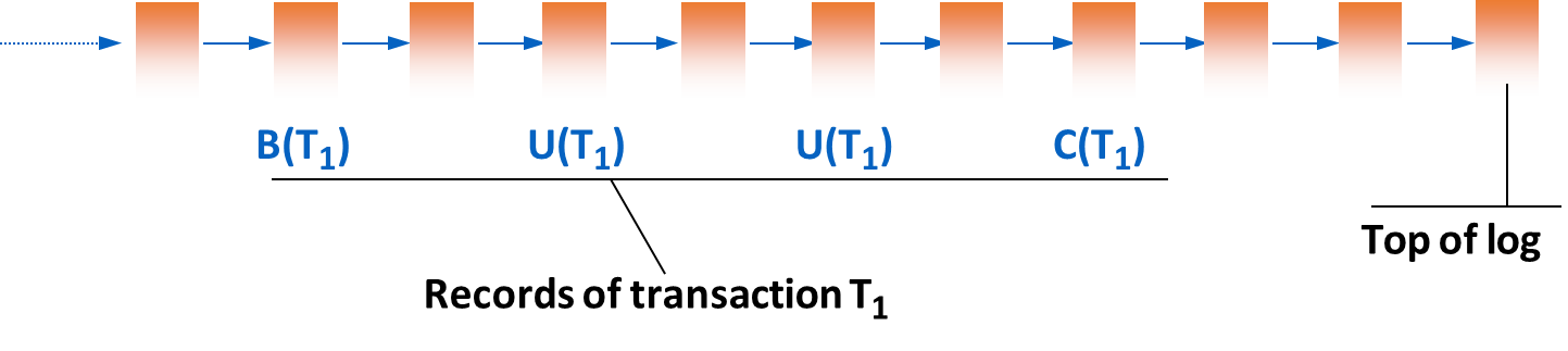
The log contains various types of records:
- Transactional Commands: records concerning the lifecycle of transactions.
: Begin Transaction : Commit Transaction : Abort Transaction
- Data Operations: records of data modifications.
: Update by transaction on object , with Before-State and After-State . : Insert by of object with After-State . : Delete by of object with Before-State .
- Recovery Actions: records that mark significant points in the log.
: Marks a backup of the database. : Marks a checkpoint, listing all transactions (by their identifiers) that were active at the time of the checkpoint.
Transactional Rules for Reliability
To guarantee that the log can be used for recovery, all write operations must follow strict rules.
Rules
Commit Record Rule: A
commitlog record () must be written to the log synchronously (i.e., with a forceoperation). The transaction is not considered officially committed until this log record is safely in stable memory.Write-Ahead-Log (WAL) Rule: The log record representing a data modification (specifically, the
before-state) must be written to the log before the modification itself is written to the database on disk. This ensures that the system always has the information needed to UNDO an operation.Commit Rule: The log record containing the
after-stateof a modification must be written to the log before thecommitrecord for that transaction is written. This ensures that the system always has the information needed to REDO a committed transaction.
Writing to Log and Database
The timing of when the database buffer pages are written to disk relative to the transaction’s lifecycle has significant implications for what kind of recovery is needed.
-
Writing to DB before commit: In this case,
REDOis not necessary, because any changes from committed transactions are already on disk. However,UNDOis required for any uncommitted transactions whose dirty pages made it to disk.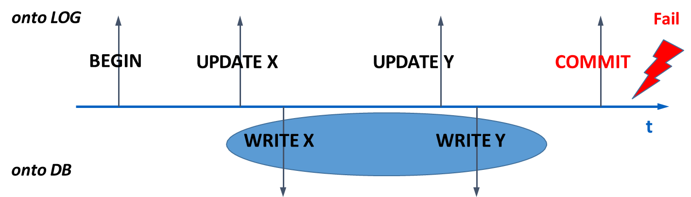
-
Writing to DB after commit: Here,
UNDOis not necessary because no uncommitted changes are ever written to disk. However,REDOis required to ensure the changes of committed transactions are applied after a crash.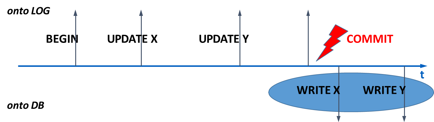
-
Writing to DB at arbitrary times: This is the most flexible and common approach, as it allows for optimizing buffer management. However, it requires both
UNDOandREDOfor recovery in the general case.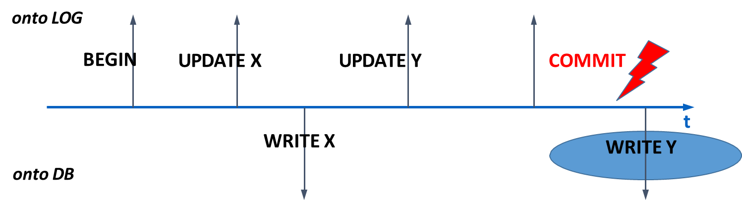
Recovery After Failures
Failures are categorized based on their severity, and each type requires a different recovery procedure.
- Soft Failure: Loss of the contents of main memory (e.g., due to a system crash or power outage). The contents of secondary storage (disk) are intact.
- Recovery: Requires a warm restart. The log is used to
REDOcommitted transactions andUNDOuncommitted transactions.
- Recovery: Requires a warm restart. The log is used to
- Hard Failure: Failure or loss of secondary memory devices (e.g., disk failure).
- Recovery: Requires a cold restart. The database is first restored from the most recent backup (
dump), and then the log is used to roll forward all transactions that committed since the backup was taken.
- Recovery: Requires a cold restart. The database is first restored from the most recent backup (
- Disaster: Loss of the stable memory itself (i.e., both the live database and its backups/logs are destroyed). Recovery from this is a complex process related to disaster recovery planning and is not covered here.
Checkpointing
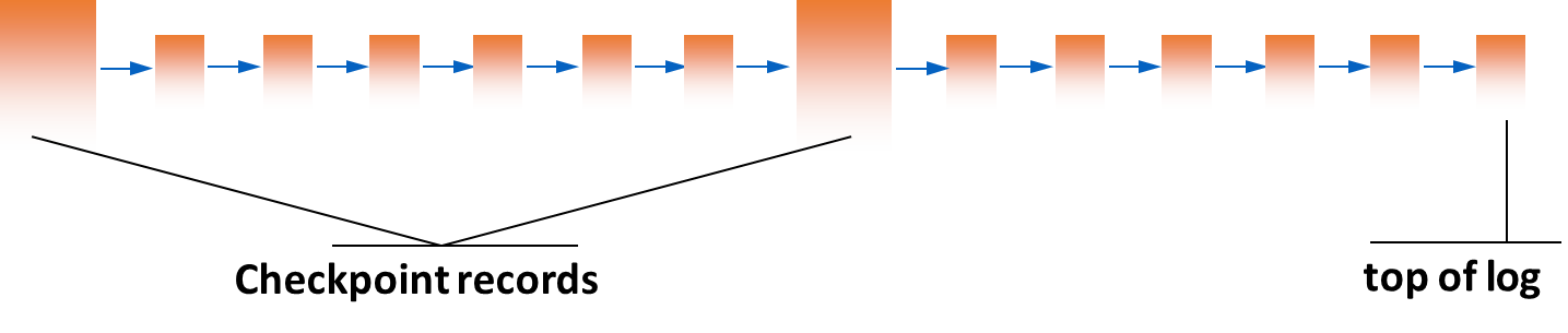
Scanning the entire log from the beginning of time during recovery would be incredibly inefficient. A checkpoint is a mechanism to limit the amount of log that needs to be processed.
Checkpoint
A checkpoint is a point in time where the DBMS forces all modified buffer pages from committed transactions to be written to disk. It creates a record in the log,
CKPT(T1, T2, ... Tn), which lists all transactions that were active (i.e., not yet committed) at the time of the checkpoint.
The goal is to establish a consistent point from which recovery can begin, knowing that all changes before this point from committed transactions are safely on disk. This shortens the recovery time significantly, as the recovery process only needs to consider the log from the last checkpoint forward.
Steps
- Temporarily suspend the acceptance of new
commitandabortrequests.- Force all “dirty” buffer pages that were modified by already committed transactions to mass storage.
- Write a
CKPTrecord to the log, containing the identifiers of all transactions that are still in progress. This write must be synchronous (force). No new transactions can start during this step.- Resume normal operations.
This process guarantees that for all committed transactions, their data is on disk, and any “half-way” transactions are explicitly listed in the stable checkpoint record.
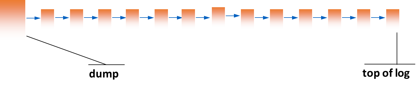
Dump
A dump is simply a complete backup copy of the entire database, typically created during off-peak hours (e.g., at night or on weekends). The availability of a new dump is recorded in the log. Dumps are essential for recovering from hard failures.
There are several strategies for creating dumps:
- Full Dump: A complete copy of the entire database is made. This is simple but can be time-consuming and requires significant storage space.
- Incremental Dump: Only the changes made since the last dump are saved. This is more efficient in terms of time and storage but requires a more complex recovery process, as it may need to apply multiple incremental dumps to restore the database to a consistent state.
- Differential Dump: Similar to incremental dumps, but it captures all changes made since the last full dump. This strikes a balance between full and incremental dumps, allowing for faster recovery than incremental dumps while still being more efficient than full dumps.
Recovery Procedures
The recovery process depends on the type of failure and the state of the database at the time of the failure. The two main types of recovery are warm restart (for soft failures) and cold restart (for hard failures).
| Type | Description |
|---|---|
| Warm Restart | Used for recovering from soft failures by replaying the transaction log. |
| Cold Restart | Used for recovering from hard failures by restoring from a dump. |
Warm Restart (Soft Failure Recovery)
A warm restart is initiated after a soft failure (main memory loss). It uses the transaction log to bring the database back to a consistent state.
Algorithm
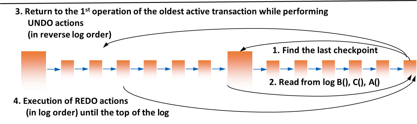
- Find the last checkpoint in the transaction log.
- Initialize two sets:
UNDO-set: Initially contains all transactions listed as active in the checkpoint record.REDO-set: Initially empty.- Scan the log forward from the checkpoint to the end (the “top of log”):
- If a
B(T)(Begin Transaction) record is found for a transactionT, addTto theUNDO-set.- If a
C(T)(Commit) orA(T)(Abort) record is found for a transactionT, moveTfrom theUNDO-setto theREDO-set.- At the end of this scan, the
UNDO-setcontains all transactions that were active at the time of the crash (incomplete), and theREDO-setcontains all transactions that completed after the checkpoint.- Perform UNDO: Scan the log backwards from the end to the oldest action of any transaction in the
UNDO-set. For each modification record belonging to a transaction in theUNDO-set, apply theBEFORE-STATEto undo the change.- Perform REDO: Scan the log forwards from the checkpoint to the end. For each modification record belonging to a transaction in the
REDO-set, apply theAFTER-STATEto redo the change.
Cold Restart (Hard Failure Recovery)
A cold restart is performed after a hard failure (disk loss).
Algorithm
- Restore from Backup: Retrieve the most recent database
dumpand restore it to a new secondary storage device.- Roll Forward: Starting from the log record corresponding to the dump, scan the log forward to the point of failure. Execute the REDO phase of recovery for all committed transactions found in the log. This brings the database to the state it was in just before the crash.
- Execute a Warm Restart: After rolling forward, the database is in a state equivalent to just before a soft failure. A standard warm restart is then performed to
UNDOany transactions that were incomplete at the time of the crash.