Software design encompasses the critical task of making structural decisions that shape the architecture of a software system. This process involves defining the various components or modules that make up the software, elucidating the relationships among these components, and determining how they will interact with each other. Effective software design is pivotal for ensuring that a system is both functional and maintainable.
The main objectives of software design are multi-faceted. It aims to support trade-off analysis by employing reasoning-enabling structures, which allow developers to evaluate different design choices based on specific criteria. Additionally, a well-crafted software design facilitates concurrent development, meaning that different teams can work on separate components simultaneously without conflicts. This is achieved by clearly separating responsibilities among components, which not only enhances collaboration but also increases the overall understandability of the solution. The culmination of this design process is the production of the Design Document (DD), a comprehensive document that outlines the architectural decisions made, the rationale behind them, and how the various components will function together.
Software Architecture
Software Architecture (SA) can be defined as the foundational set of structures necessary for reasoning about a software system.
Quote
These structures include software elements, the relationships between them, and their respective properties.
Bass et al. (2021)
SA serves as a crucial tool for understanding and analyzing systems, allowing stakeholders to visualize and evaluate the system’s overall structure and functionality.
An effective SA is composed of a well-defined set of structures, each of which plays a role in the system’s performance and reliability. These structures can be viewed as analogs to various natural systems, where different perspectives reveal unique properties yet remain interconnected. For example, consider the architecture of the human body. When examining the human body, one can observe different views (such as the skeletal system, muscular system, and circulatory system). Each view possesses distinct properties and functions. However, these views are inherently related and interdependent, together forming a comprehensive understanding of the “architecture” of the human body.
Important
This analogy underscores the importance of software architecture: just as the various structures of the human body work together to create a functioning organism, the diverse components of software architecture must interact seamlessly to produce a cohesive and efficient software system.
Set of Structures in Software Architecture
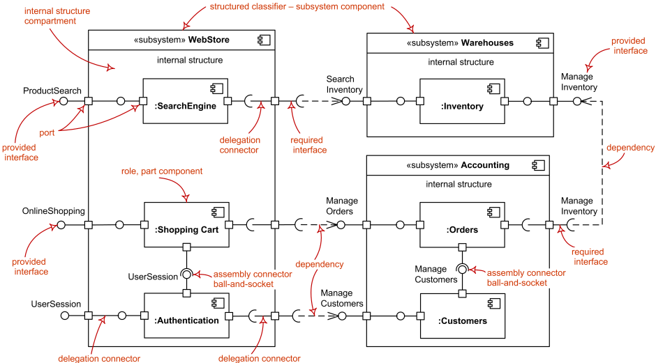
In software architecture, different structural perspectives are used to comprehensively design and understand a system. These structures include component-and-connector structures, module structures, and allocation structures. Each structure offers a unique view into the software, covering aspects like behavior, organization, and system deployment, ultimately enhancing the system’s robustness, clarity, and maintainability.
Component-and-Connector
The component-and-connector (C&C) structure focuses on organizing the system as a network of interacting runtime elements, with components and connectors at its core. This structure represents how a system operates when it is running, illustrating both the computational units (components) and the communication mechanisms (connectors) between them.
Definition
- Components are the primary units of computation within a system. They perform the core functions and can include entities like clients, servers, and services.
- Connectors represent the communication pathways or protocols that facilitate interaction between components. Common types of connectors include request-response mechanisms, pipelines, and asynchronous messaging.
Example
For instance, in the multi-process architecture of Chromium (as detailed in the Chromium documentation), C&C structures can help answer critical questions about the system’s operational dynamics:
- What are the major executing components, and how do they interact at runtime?
- What shared data stores exist, and which parts of the system are replicated?
- How does data flow and progress throughout the system?
- Which components are designed to operate in parallel, and how does the system’s structure adapt over time?
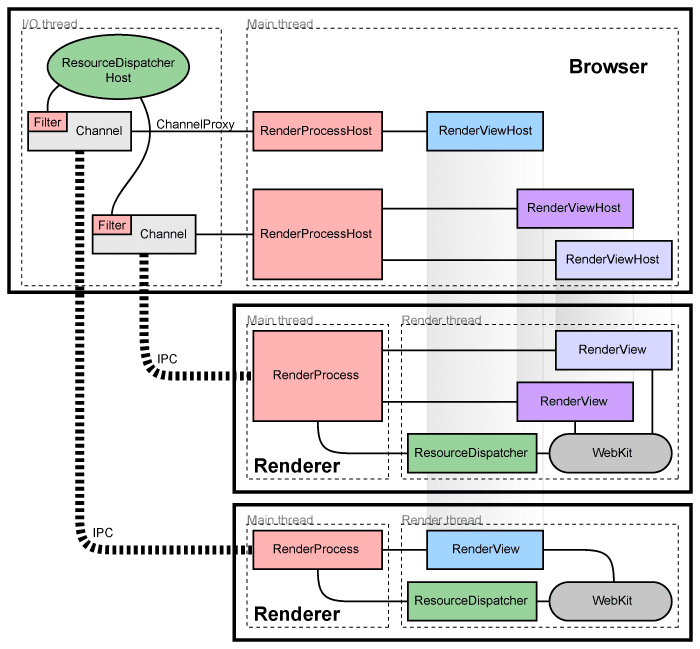
Component-and-connector structures also allow architects to analyze runtime attributes such as availability, performance, and fault tolerance, essential for designing scalable and resilient systems.
Unified Modeling Language (UML) offers diagrammatic representations that simplify complex interactions within C&C structures, providing visual insights into component behavior and communication. Two commonly used UML diagrams for this purpose are UML component diagrams and UML sequence diagrams.
-
UML Component Diagrams: These diagrams represent the physical components of a system, showcasing their roles, relationships, and dependencies. They provide a high-level view of how components connect and interact, particularly useful for understanding large system structures.
-
UML Sequence Diagrams: Sequence diagrams emphasize the sequence of interactions over time among components. They illustrate the step-by-step flow of operations, giving insight into the order of interactions within a use case.
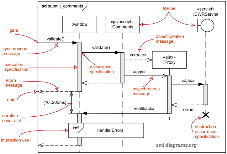
Sequence Diagram Example
The UML sequence diagram below represents a simple online shopping interaction, depicting how various components interact to complete the purchase flow.
This sequence demonstrates how the
Customerinteracts with theCustomerUIto browse products, add them to a cart, and finalize the purchase. TheCustomerUIthen communicates with theShoppingCartcomponent, which interacts withOrdersto prepare the order, check product availability withInventory, and retrieve customer details fromCustomers. This level of detail clarifies how data flows through each component, helping designers validate the correctness and efficiency of the interaction flow.

Module Structures
Module structures represent the organization of a system as a collection of code and data units, or modules, that are logically related and serve distinct purposes. Modules in a system serve as implementation units that enable the development process to be divided into manageable sections, with each section corresponding to a specific functional area or responsibility.
Examples of modules include software entities such as packages, classes, functions, libraries, layers, and database tables. Each of these modules interacts with other modules through established relationships, commonly defined by use (dependency), is-a (generalization), and is-part-of (composition) relationships.
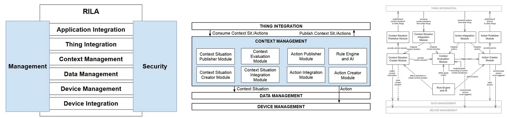
Example of Module Structure: IoT Layered Architecture (RILA)
The Internet of Things (IoT) Reference Layered Architecture (RILA) is an example of a layered modular structure, as detailed in the InfoQ article on IoT architecture. In a layered architecture, modules are organized in hierarchical layers, where each layer can interact with the layer directly below it and can be accessed by the layer directly above. This organization brings a clear separation of concerns, allowing for different teams to work independently on different layers while maintaining a cohesive structure. Layers are arranged according to their use relationships, enabling a clean, ordered interaction among components and making it easier to identify the primary focus of each layer at a glance.
This organization allows developers to answer crucial questions, such as:
- What is each module’s primary functional responsibility?
- What dependencies exist between modules?
- Which modules are related through inheritance or generalization?
Module structures are essential for understanding a system’s modifiability. By analyzing module dependencies and relationships, developers can predict how a change in one module might impact the others, which is crucial for maintaining flexibility and ease of updates within the system.
UML provides various types of diagrams to represent module structures, helping visualize dependencies, relationships, and organizational hierarchy. Common UML diagrams for module structures include:
-
Class Diagrams: Depict the system’s classes, their attributes, methods, and relationships, including inheritance, association, and composition. Class diagrams are instrumental in identifying functional responsibilities within each class and clarifying module relationships.
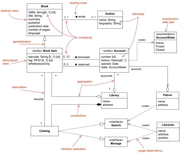
-
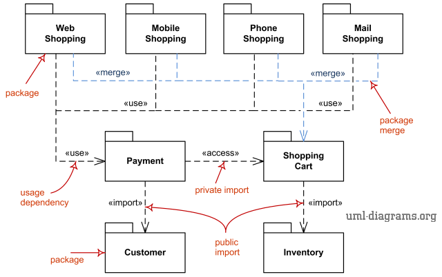
Package Diagrams: Show the organization of classes and components into packages, representing higher-level module structures. Package diagrams clarify how various functional areas of a system are grouped, simplifying large systems’ structure by defining logical layers.
-
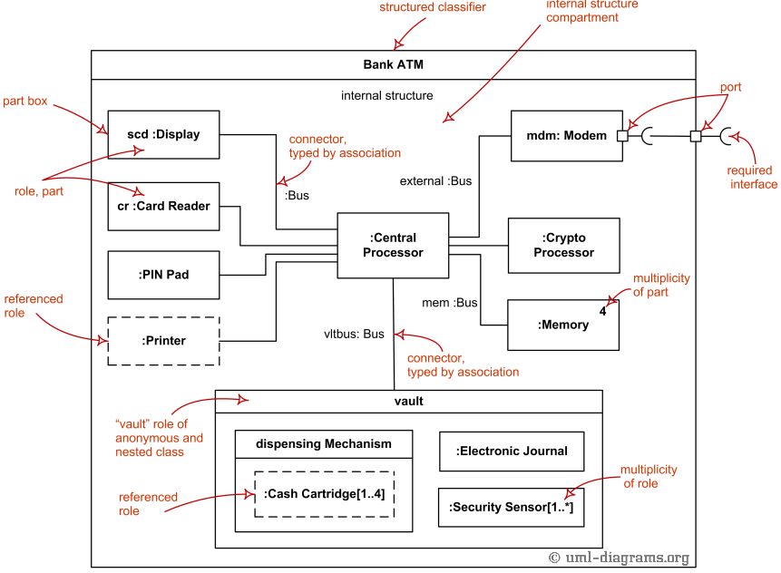
Composite Structure Diagrams: Illustrate the internal structure of a classifier, showing how its parts interact to fulfill a specific role. These diagrams can model the collaborations within a module, making it useful for detailed design of complex modules.
Module structures, when combined with these UML representations, offer a powerful means of designing and reasoning about software architecture. They not only facilitate the allocation of responsibilities and the identification of dependencies but also enable system-wide impact analysis, thereby supporting the system’s adaptability and scalability.
Allocation Structures
Allocation structures define how software components, as represented in the component-and-connector (C&C) or module structures, map onto entities outside of the software itself, such as hardware, file systems, or teams. These structures are crucial in bridging the gap between abstract software design and real-world implementation, ensuring that the software integrates smoothly with physical, organizational, and operational environments. Examples of allocation structures include:
-
Deployment Structure: Maps software components onto hardware resources, such as servers, databases, and network configurations. This structure is essential for defining how components are physically distributed across hardware and how they communicate in real-time. Deployment structures are key in identifying potential performance bottlenecks, resource requirements, and ensuring optimal distribution of computational load.
-
Implementation Structure: Organizes software modules in a way that supports version control, file structure, and configuration management. Implementation structures ensure that all elements of the software are stored, tracked, and integrated effectively, supporting collaboration across teams and environments.
-
Work Assignment Structure: Defines how tasks, modules, or components are distributed among development teams or organizational units. This structure is crucial in project management as it helps identify team responsibilities, optimize collaboration, and track progress, contributing to efficient software delivery.
Deployment Structure
The deployment structure details how the software system’s hardware is organized and how the software components are assigned to different hardware nodes. Typically developed by software architects, networking engineers, and system engineers, the deployment structure includes a system’s topology, illustrating the distribution of components and identifying performance bottlenecks. In the deployment phase, software architects and engineers create deployment diagrams to visualize these assignments, facilitating analysis of the system’s robustness and responsiveness.
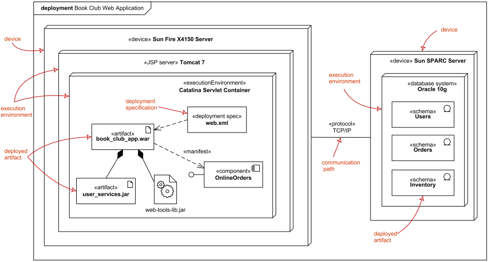
A UML deployment diagram represents the configuration of runtime processing nodes and the software components deployed on these nodes. Nodes, in UML, represent hardware devices (e.g., servers, databases, client machines) and the software elements they host. The diagram below shows an example of a deployment structure, illustrating how software applications communicate over protocols like HTTP and TCP/IP to support complex distributed systems:
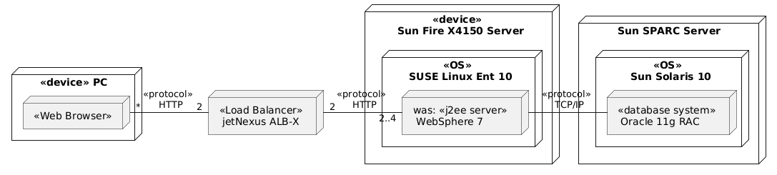
In this deployment example, software components such as a web browser, load balancer, and J2EE server are hosted on distinct hardware nodes and communicate via HTTP and TCP/IP protocols. The deployment structure not only clarifies the system’s topology but also helps in identifying areas where network latency or hardware limitations might impact performance.
Summary of Software Architecture Structures
Each structure type in software architecture serves a distinct purpose, contributing to different aspects of system design, analysis, and deployment. The table below summarizes the major classes of structures, their specific types, and their applications.
Structure Classes Structure Types Element Types Relations Purpose Module Structures Composite structures, package diagrams Modules, packages Is a submodule of, uses Supports resource allocation, project planning, and encapsulation Class diagrams Classes Is-a, is part of Facilitates object-oriented development and planning for extensions Layered structures Layers Can use, provides abstractions to Enables incremental development and layer-based responsibility separation Data models Data entities One-to-one, many-to-one, etc. Supports engineering of consistent, high-performance global data structures Component & Connector Structures Component diagrams Components offering services Provided and required interfaces Supports performance and robustness analysis, resource allocation, and project planning Sequence diagrams Processes/threads Synchronous and asynchronous messages Analyzes resource contention and identifies parallelism opportunities Allocation Structures Deployment diagrams Components, hardware/software environments Allocated to Evaluates performance, security, and robustness in deployment Implementation structures Modules, file structures Stored in Facilitates configuration control, integration, and testing activities Work assignment structures Modules, organizational units Assigned to Supports project management and enhances development efficiency
Through careful planning and use of these structures, software architects can design systems that are scalable, maintainable, and adaptable to evolving requirements. By defining deployment, implementation, and work assignment strategies, allocation structures allow developers to anticipate and manage potential challenges in integrating software with hardware and team workflows, ultimately improving the system’s performance and development process efficiency.
Analysis of the SmartLightingKit System
The SmartLightingKit is a lighting management system tailored for large buildings, allowing local and remote control of lights in individual rooms. The system includes several components that work together to enable flexible lighting management and authorization control. Each component has a distinct role within the system architecture, supporting features such as light control, authorization management, room mapping, and user interaction.
System Structure and Light Control
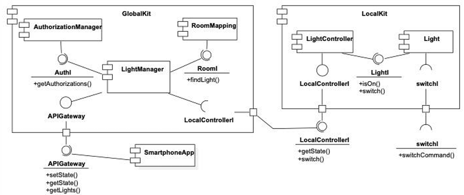
The diagram illustrates components supporting the switching on/off of lights and monitoring their status. From the analysis of the components involved, we observe a distributed approach where each room has a LocalKit component installed on a terminal within the room. Each LocalKit interacts with a GlobalKit component, installed on a central terminal, allowing a centralized approach to manage and track lights across multiple rooms.
GlobalKit acts as the central control unit and maintains components like RoomMapping for tracking lights’ locations, AuthorizationManager for handling user permissions, and LightManager to coordinate interactions with LocalKit instances. This system design supports scalable management and ensures that both local and global interactions are handled effectively.
System Components and Interactions
GlobalKit communicates with other components via the APIGateway interface, which facilitates remote operations (e.g., using a smartphone app). The APIGateway acts as a bridge, forwarding requests from authorized users to the appropriate local or global components. SmartphoneApp, the mobile application interface, allows users to check light statuses, turn lights on or off, or initiate automated routines.
LocalKit components operate within each room terminal, exposing the LocalControllerI interface that interacts with LightController and the individual Light components. This structure allows LocalKit to control each light locally through switchCommand, facilitating both remote and direct light control actions.
Operations Analysis
Each component supports specific operations that allow the system to perform light control and user management effectively. Key operations include the following:
-
APIGatewayoffers:getLights(userID): Takes auserIDas input and returns a list of lights that the user can control.getState(userID): Returns the current states (e.g., on or off) of lights accessible to the user.setState(userID, lightID, state): Sets a specific light’s state to on or off based on user permissions.
-
AuthIprovides:getAuthorizations(userID): Retrieves authorization details for the specified user, returning the rooms and correspondingLocalKitinstances they can access.
-
RoomIincludes:findLight(roomID): Takes aroomIDand returns the list of lights within that room, enabling location-based light control.
-
LocalControllerIandLightIenable control at the room level, including:switch(lightID): Allows theLocalKitto switch the light on or off directly.getState(lightID): Retrieves the on/off state of a specific light.
-
SwitchIis an interface supporting:switchCommand: Triggers physical actions on the light, facilitating direct switching.
These operations allow for granular control over light management and ensure that only authorized actions are performed by validated users.
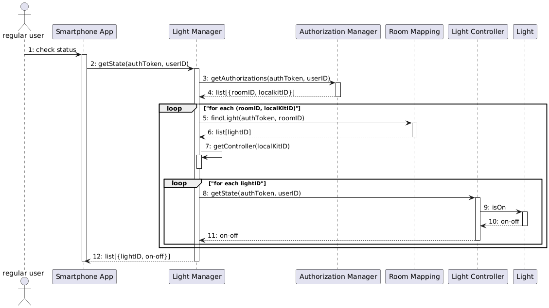
Sequence Diagram: Checking Light Status
When a user wants to check if any lights they control are still on using the SmartphoneApp, the following sequence diagram illustrates the interactions between software components:
Accommodating the New Requirement for Real-Time Updates
To incorporate the new requirement (NewReq) for real-time status updates on the lights, the current architecture must be modified to enable the SmartphoneApp to activate or deactivate update notifications for all controllable lights. However, due to the lack of a push mechanism in the existing design, the implementation would require a workaround through continuous polling.
The sequence diagram below outlines the polling-based approach for checking light status updates:
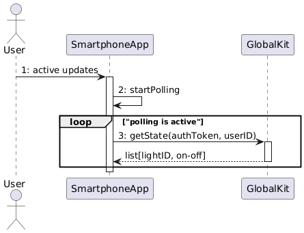
- User Initiation: The user activates the real-time update feature via the
SmartphoneApp. - Polling Loop: The
SmartphoneAppcontinuously sends requests to theAPIGatewayto check the status of each light. - Authorization and Light State Retrieval: The
APIGatewayrequests authorization details for the user fromGlobalKit, which includes room and light identifiers. - Status Collection from Lights: For each authorized light, the
LocalKitchecks the current state of each light through itsisOncommand, and the results are sent back to theAPIGateway. - Display Updates: The
SmartphoneAppdisplays any updated light status information for the user.
The primary disadvantage of this polling-based solution is the high communication overhead. Since status updates are continuously polled, even when no changes occur, the process generates unnecessary network traffic. This not only puts a strain on the APIGateway, GlobalKit, and LocalKits but also may reduce system performance and responsiveness, especially as the number of controlled lights and active users grows.
By analyzing the component-and-connector (C&C) structures, we gain valuable insights into system operations and can reason about possible extensions or improvements. Through this exercise, we identified a few key takeaways:
- System Understanding: C&C structures provide a clear picture of how components interact, which components are potentially replicated, and how components could be allocated to different execution environments.
- Operation Specification: These structures allow us to identify and define necessary operations early in the development phase, supporting efficient implementation and integration.
- Change Impact Analysis: They help us evaluate the effect of new requirements on the system and identify potential bottlenecks or areas requiring enhancement, such as the need for a more efficient real-time update mechanism.
- Exploring Architectural Options: The exercise prompts us to consider new architectural options, such as implementing a push notification service. This would allow the system to only send updates when a light’s state changes, significantly reducing the communication burden.