“An architectural style determines the vocabulary of components and connectors that can be used in instances of that style, together with a set of constraints on how they can be combined. These can include topological constraints on architectural descriptions (e.g., no cycles). Other constraints—say, having to do with execution semantics—might also be part of the style definition.”
Garlan & Shaw (1994)
Client-server
The client-server model is a fundamental architectural paradigm used in computing to organize the interaction between two distinct types of components: clients and servers. In this structure, the client and server each play specific roles that contribute to an efficient, distributed computing environment. The client is responsible for initiating requests for resources or services, while the server is dedicated to processing these requests and providing the necessary responses.
graph RL
    subgraph "Host A"
        A[Client]
    end
    subgraph "Host B"
        B[Server]
    end

    A -- request --> B
    B -- response --> A
This model is particularly valuable in scenarios where multiple users or systems need access to a centralized resource. For example, a shared database or file system can be accessed by multiple clients through a single server, which maintains and manages the resource. This setup is also useful for accessing remote applications, such as email servers, or when a system must provide a centralized service like authentication or authorization. By centralizing functionality within a server that multiple clients can access, the client-server model provides an organized and scalable way to support shared resources and services.
Thin vs. Fat Clients
The client-server architecture can vary in terms of how functionality and processing load are distributed between the client and server. This distribution often determines whether a client is considered “thin” or “fat.”
Definition
Thin Client: In a thin client setup, the client is primarily responsible for displaying the user interface (UI) and sending requests over the network, while the server handles most of the application logic and data processing. This type of client-server model is commonly used when network bandwidth is strong and server resources are robust, as most of the workload is on the server side.
Fat Client: Conversely, in a fat client configuration, more processing and application logic are handled on the client side. The client is capable of executing substantial operations independently of the server, which reduces the load on the server but requires more powerful client devices. Fat clients are typically used in environments where network connectivity may be limited or variable, as they can function with minimal server interaction for certain tasks.
This flexibility in design allows for configurations suited to the needs of various use cases, balancing factors like server capacity, network reliability, and the specific tasks performed by clients.
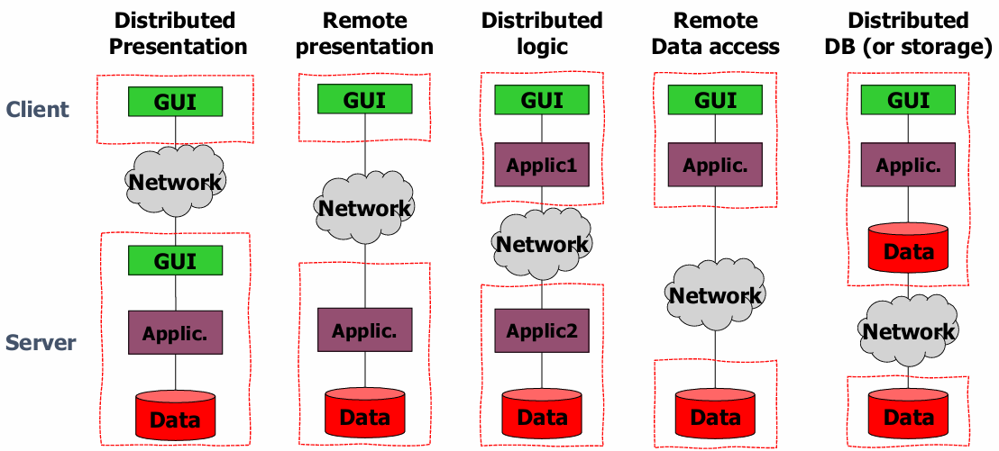
The client-server architecture can be organized in different ways depending on how the application layers (presentation, logic, and data) are distributed across the client and server. Here are common configurations within client-server structures:
Distributed Presentation: Here, the presentation layer is split across the client and server. The client may handle some aspects of the user interface (UI) while the server manages the back-end processing.
Remote Presentation: In this setup, the presentation layer is handled almost entirely on the client side, while the application logic and data are hosted on the server. The client primarily sends and receives data over the network but maintains control over the UI.
Distributed Logic: The application logic is split between the client and server. This allows for shared processing, where both client and server work together to execute application functions.
Remote Data Access: Here, the application logic is located on the client, which directly accesses data stored on the server. This model is often used when clients need frequent or direct interaction with large datasets.
Distributed Database (DB): This setup distributes database components across both client and server. Both client and server may perform data processing tasks, which can reduce the load on any single component and improve scalability.
Designing and implementing a robust client-server model requires addressing several critical technical aspects. Effective solutions for these issues contribute significantly to the reliability, scalability, and usability of the system.
A well-documented and thoughtfully designed interface is essential for smooth client-server interactions. Clear interfaces ensure that both client and server components understand the format, structure, and behavior expected from requests and responses. This documentation typically includes details on request parameters, response structures, error handling, and protocols, which allows developers to build compatible and reliable client applications.
Scalability is a key requirement in client-server architectures, especially when the server must support multiple clients at once. Effective handling of simultaneous requests from multiple clients involves choosing an appropriate concurrency model, such as forking or thread pooling.
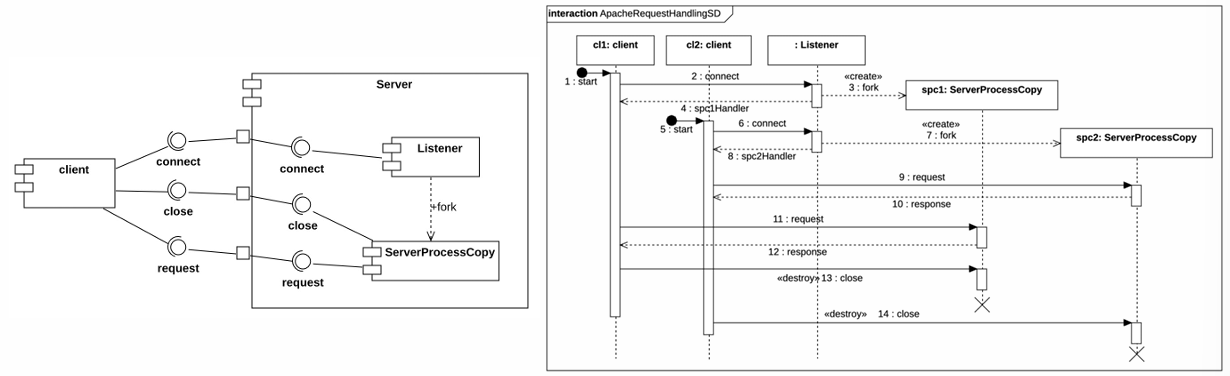
Forking: In this model, a new process is created for each client request. Forking can provide strong isolation between requests, as each process runs independently. However, it can be resource-intensive, as each new process consumes memory and processing power.
Thread Pooling: In thread pooling, a fixed number of threads are created and reused to handle client requests. Thread pooling is often more efficient than forking, as it reduces the overhead associated with creating and destroying processes. This approach is generally suitable for high-performance servers that need to handle large volumes of client requests without unnecessary resource consumption.
Each approach has its trade-offs, and the choice between them often depends on the expected server load, available resources, and the complexity of each request. Forking provides better isolation but at a cost in terms of memory and processing power, while thread pooling is efficient but requires careful management of shared resources to avoid issues such as race conditions or deadlocks.
Interface Design
An interface serves as a boundary across which components in a software system interact. By defining this boundary clearly, the interface allows different parts of the system to communicate and work together while minimizing dependencies and potential disruptions. Properly defined interfaces are essential in software architecture, impacting several key qualities, including maintainability, usability, testability, performance, and integrability. The goal of interface design is to encapsulate component implementations, so that changes within a component do not ripple across the system, impacting other components.
Two primary principles guide effective interface design:
Information Hiding: Each component should only expose what is necessary for interaction, concealing internal details. This helps protect the component from changes in other parts of the system.
Low Coupling: Interfaces should minimize dependencies between components, allowing them to interact without being tightly linked. This separation makes it easier to modify, replace, or update components without affecting the overall system.
Designing a robust interface involves several considerations that ensure it is both useful and resilient:
Contract Principle: Each resource, whether an operation or data structure, added to an interface represents a commitment. This means the interface must continue to support these resources, providing reliability and stability to components that rely on it.
Least Surprise Principle: The behavior of an interface should align with reasonable expectations to avoid confusing users or developers. This implies intuitive design and consistency with established conventions.
Small Interfaces Principle: Minimizing the resources and functions exposed by an interface helps reduce complexity and limits potential misuse. Small interfaces are easier to understand, test, and maintain.
Key elements to define in an interface include the interaction style (e.g., sockets, RPC, REST), the representation and structure of exchanged data, and error handling mechanisms. These factors determine how components will communicate, ensuring smooth interactions across different parts of the system.
Communication Styles
Interfaces can support various communication styles, each suited to different use cases and system requirements.
Sockets
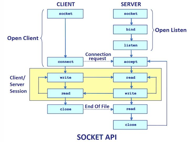
Socket programming allows for direct, bidirectional communication between two components after a connection is established. Both components must agree on the protocol, which is the sequence and structure of message exchanges. Socket-based communication is particularly useful for real-time, low-latency applications that need continuous, two-way data exchange, such as chat applications or multiplayer games.
Example
For example, in a typical socket connection:
A client initiates a connection to the server, which listens on a specific port.
Once connected, data can be sent back and forth until the connection is closed by either party.
This approach offers flexibility but requires careful management of connection states and error handling to ensure reliability and prevent communication breakdowns.
Remote Procedure Call and Remote Method Invocation
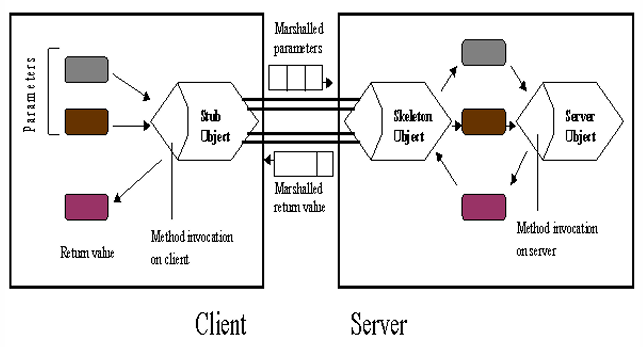
Remote Procedure Call (RPC) and Remote Method Invocation (RMI) provide a communication style that resembles local function or method calls. With these methods, remote operations can be invoked as if they were local, making distributed applications more seamless for developers. This setup requires two main components:
Stubs: Client-side proxies that present the remote methods as local calls.
Skeletons: Server-side handlers that receive the method calls and execute them on the server.
Example
An example in Java might involve a simple banking system where the client interacts with a remote AccountManager to access account details:
import java.rmi.*;public class Client { public static void main(String[] args) { try { String name = "Jack B. Quick"; Account account = manager.open(name); float balance = account.balance(); } catch(Exception e) { e.printStackTrace(); } }}
Here, manager and account act as stubs, representing the remote AccountManager and Account objects, while the server is the actual remote object that performs the open operation. This abstraction allows developers to work with the interface without needing to manage complex network operations directly.
public class AccountManagerImpl … {
    public Account open(String name) … { //… }

    public static void main(String[] args) { //…
        AccountManagerImpl server = new AccountManagerImpl(_hostName);
        Naming.rebind("//" + _hostName + "/AccountManager", server);
        //…
    }
}
Here, server is the remote object that executes the open operation, while the AccountManagerImpl class manages the server-side logic. This separation of concerns allows for clear communication between client and server components, enhancing the overall system architecture.
REST: Representational State Transfer
Definition
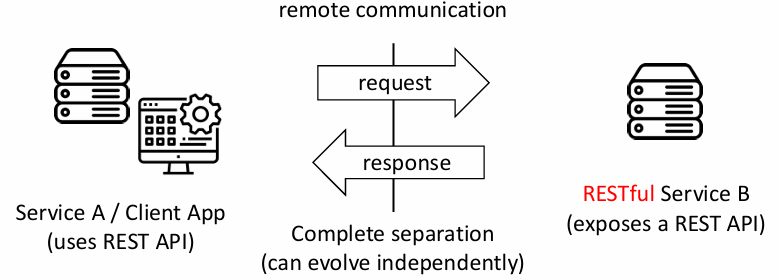
Representational State Transfer (REST) is an architectural style developed specifically for designing Application Programming Interfaces (APIs) that enable communication between distributed systems. REST promotes a clear separation between systems and components that may differ in platforms, languages, or configurations, facilitating interoperability and scalability in web-based applications.
RESTful principles were introduced by Roy T. Fielding and Richard N. Taylor, who aimed to create a standardized framework for building modern web architectures.
REST APIs are characterized by simplicity, standardization, statelessness, and scalability. These features provide a powerful structure that has become a popular industry standard for API design.
Simplicity and Standardization: REST APIs rely on HTTP, which is widely supported and well-understood. Data exchange typically occurs in JSON format, which is easy to read and parse. Additionally, REST defines clear request/response conventions, making communication straightforward and reducing the need for custom protocols.
Statelessness: REST APIs are designed to be stateless, meaning that each client request is independent and contains all necessary information. The server does not maintain client-specific data between requests, which simplifies server management and supports horizontal scalability.
Scalability and Performance: Statelessness enables REST APIs to handle large volumes of requests, enhancing scalability. REST also supports caching, which improves performance by allowing frequently requested resources to be stored and reused.
Types of REST API Requests (CRUD Operations)
REST APIs use specific HTTP methods to carry out the four main operations, known as CRUD (Create, Read, Update, Delete):
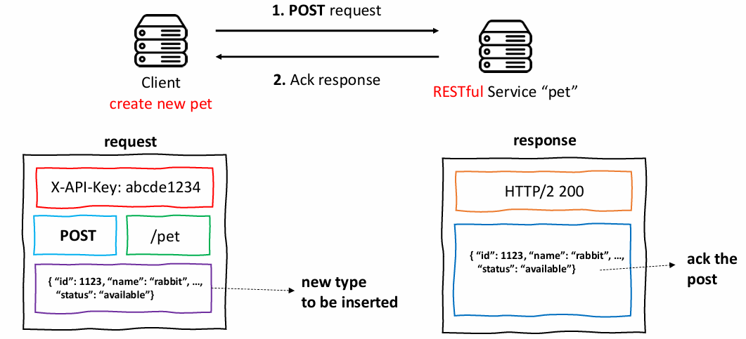
POST: Used to create a new resource.
GET: Used to retrieve or read an existing resource.
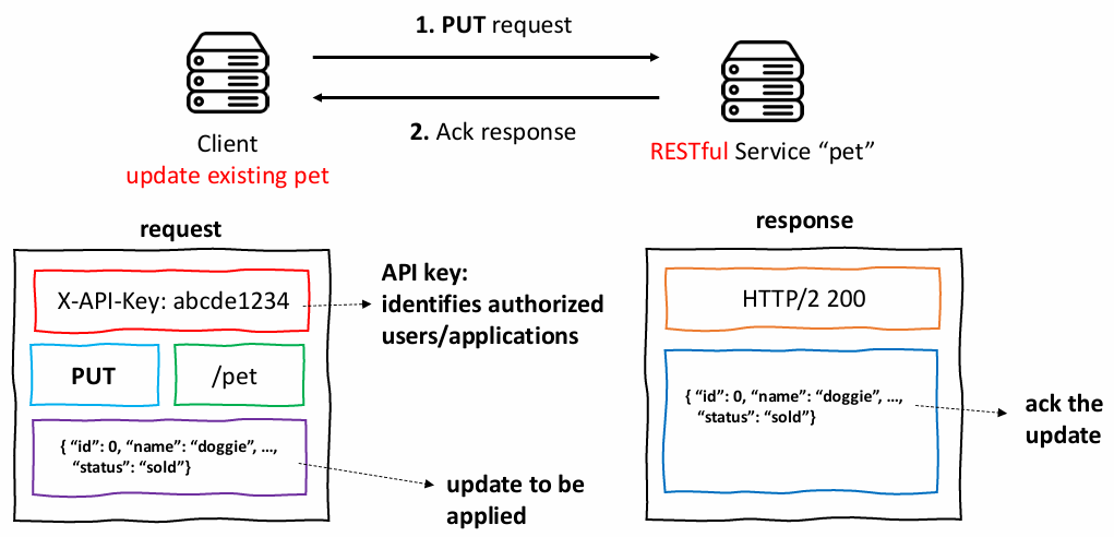
PUT: Used to update an existing resource.
DELETE: Used to remove a resource.
These operations provide a clear, consistent approach to manipulating resources, allowing developers to build predictable and well-structured applications.
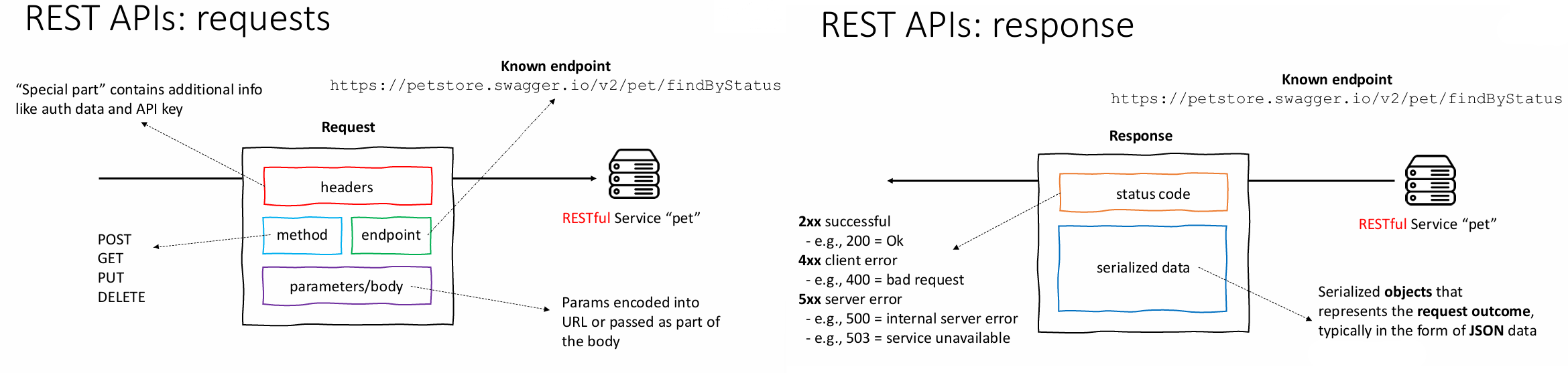
A typical REST API interaction involves sending a request to a specific endpoint (often a URL identifying the resource) and receiving a response. The response generally includes an HTTP status code indicating success or failure, along with a message body, commonly in JSON format, containing any requested data.
Example 1: GET Request
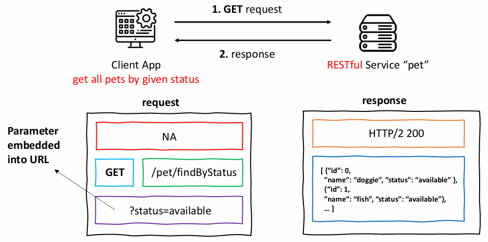
A GET request to retrieve data about pets available for adoption:
Request
curl -X GET 'https://petstore.swagger.io/v2/pet/findByStatus?status=available'
     -H 'accept: application/json'
Response
HTTP/2 200date: Fri, 13 Oct 2023 16:38:33 GMTcontent-type: application/json
In this example, the client retrieves a list of pets that are available by specifying the status in the query parameter. The server returns a JSON array of pet objects matching the criteria.
In this example, the client updates the status of the pet named “doggie” to “sold.” The server then returns the updated pet information, reflecting the change.
Representation and Structure of Exchanged Data
The choice of data representation format has a direct impact on several key aspects of communication between systems, including expressiveness, interoperability, performance, and transparency. Data representations can be language-specific, which might limit compatibility, or they can be in an external format, enhancing interoperability among different systems and platforms. The three main representations—JSON, XML, and Protocol Buffers—each offer unique benefits and trade-offs, making them suitable for different types of applications.
XML
JSON
Protocol Buffers
Expressiveness
Good
Good
Good
Interoperability
Good
Good
Good
Performance
Verbose, multiple parsing passes
Compact, single-pass parsing
Very compact, binary format
Transparency
Text-based, highly transparent
Text-based, transparent
Binary format, less transparent
JSON (JavaScript Object Notation)
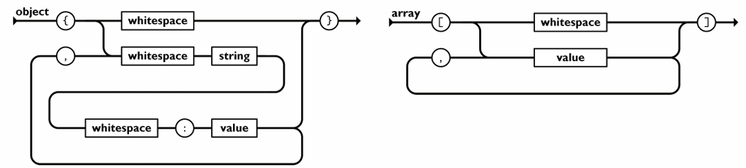
JSON is a lightweight format that supports two main constructs—objects (name-value pairs) and arrays (ordered lists). JSON is highly versatile and commonly used in APIs due to its simplicity and effectiveness in encoding structured data.
Example
For example, a JSON array representing pets in a pet store might look like this:
XML is another language-independent text format that supports nested data structures and is both highly expressive and widely interoperable. However, XML’s verbosity can slow down performance, requiring additional parsing time. XML is still a strong choice in cases where document-style data or complex hierarchical structures are needed.
Protocol Buffers, developed by Google, use a binary format rather than text, making them more compact and faster to parse than JSON or XML. This format is less human-readable but extremely efficient for transmitting large volumes of data across systems. Protocol Buffers are often used in performance-critical applications. Here is a Protocol Buffer schema for representing the same guest list:
Error handling is crucial in API design as it ensures that systems can respond to problems gracefully and maintain reliability. Various types of errors can arise:
Invalid Parameters: The operation is called with incorrect inputs.
Null Responses: The request does not return a result due to the component’s state or an execution error.
Configuration Issues: A misconfiguration, such as a database connection failure, prevents proper request handling.
Common strategies for handling these errors include raising exceptions, returning error codes, and logging issues for future analysis. Well-defined error handling policies help maintain stability and provide helpful feedback to clients.
Multiple Interfaces and Separation of Concerns
A server may provide multiple interfaces to support various functionalities and accommodate different types of users. Offering multiple interfaces enables separation of concerns, which improves system organization and can provide more controlled access to different levels of functionality. Additionally, this approach allows for flexibility as interfaces can evolve over time without disrupting clients.
Interfaces serve as contracts between clients and servers, so any change to an interface can impact compatibility. To manage evolving requirements, several strategies help maintain continuity:
Deprecation: Marking old versions for future removal while giving clients time to adapt.
Versioning: Maintaining multiple interface versions to ensure backward compatibility.
Extension: Adding new functionality to an interface without altering existing features.
These practices help ensure that changes to an interface do not disrupt existing systems and allow for gradual upgrades over time.
Documenting Interfaces
Documenting an interface is essential for helping various users understand how to interact with it effectively. Well-written documentation clarifies how to use the interface without exposing the internal workings of a component, which might lead users to depend on specific behaviors that could change over time. This is especially important in modular systems where interface stability allows developers to make changes to component internals without affecting external users.
Interface documentation serves several groups:
Developers and Maintainers of the Providing Component: These individuals need clear documentation to facilitate efficient development, updates, and troubleshooting.
Developers and Maintainers of the Using Component: They rely on the documentation to understand how to interact with the interface and integrate it into their systems effectively.
Quality Assurance (QA) Teams: For testing and system integration, QA teams need comprehensive details to verify that the system functions correctly when using the interface.
Software Architects: Architects, especially those looking to design reusable components, use interface documentation to assess whether an interface can meet specific architectural needs or be incorporated into broader systems.
OpenAPI Specification
The OpenAPI Specification (OAS) is an industry-standard format for documenting RESTful APIs, offering both human-readable and machine-readable descriptions. For example, a new developer who joins a team and needs to work with an existing service, such as a “pet” service, can refer to the OpenAPI definition. This definition provides the necessary information to understand and use the API without requiring access to the service’s source code, which saves time and minimizes learning friction.
An OpenAPI definition is typically a JSON or YAML file that describes the interface of a REST API in a standardized, structured format. This file outlines what the service can do through the interface, enabling developers to understand the API’s functions and integrate it into their applications quickly. The OpenAPI definition contains details about:
Endpoints: The paths through which resources can be accessed or manipulated.
Resources: The types of objects or data entities available through the API.
Operations: The actions that can be performed on resources, such as GET, POST, PUT, and DELETE requests.
Parameters and Data Types: Information about parameters required by each operation and their expected data types.
Authentication and Authorization Mechanisms: Security requirements and the authentication process for accessing protected resources.
The OpenAPI specification offers multiple advantages:
Standardized and Public Format: This standardization makes it easy for developers across different teams to learn and use the interface. Furthermore, a well-known format means many tools support it.
Human Readable: OpenAPI definitions make it straightforward for developers to understand API functionality, structure, and usage requirements.
Machine Readable: Tools can process OpenAPI definitions for automating tasks, such as generating tests or client code, which reduces development time and improves accuracy.
The OpenAPI Specification comes with robust tool support, making API development and maintenance much more efficient. Some common tools include:
API Validators: These tools verify that an API conforms to the OpenAPI standard, ensuring consistency and reducing errors.
Documentation Generators: Automatically creates human-readable documentation from the OpenAPI definition, making it easier for developers to understand and use the API.
SDK Generators: Generates client libraries in various programming languages, allowing developers to interact with the API more conveniently without manually coding request handling.
Client-Server Style: Handling Multiple Requests
In a client-server architecture, a server must be designed to handle multiple simultaneous requests efficiently, often from different clients. This requirement is critical in scenarios where one client may initiate a request while another is already being processed. For example, consider a banking application where multiple clients can withdraw funds from their accounts. If one client is currently withdrawing money, the server should still be able to accept and process another client’s withdrawal without unnecessary delays.
In this example, the server receives two simultaneous requests to withdraw funds from different accounts. Handling these requests efficiently involves several approaches, each with unique advantages and challenges.
The Forking Approach
A traditional solution to handling multiple client requests is the forking approach, as used by early web servers like Apache. In this model, the server creates a new process for each incoming request, which is then dedicated to that client until the request is fully processed. This “one-process-per-request” model offers a straightforward solution and provides inherent isolation; each process is entirely independent, so a slow or complex request does not delay others.
Advantages of the Forking Approach
Architectural Simplicity: This approach is easy to implement since each process handles one request, eliminating complex coordination.
Isolation and Protection: By creating separate processes, each request is isolated, ensuring that a delayed or resource-intensive request does not affect others.
Simplicity in Programming: Creating a process per request means that each process functions independently, reducing the need for complex concurrency handling.
However, as the scale of the web grew, the forking approach started to encounter scalability issues:
Resource Saturation: The number of active processes at any given time became hard to predict as the web grew. High traffic could lead to resource exhaustion, as each request spawns a new process.
High Overhead: Forking a new process for each request is computationally expensive. Frequent fork and kill operations impact performance, especially with a large number of incoming requests.
As the web evolved, this approach became less efficient, and alternative solutions were needed to improve scalability.
The Worker Pooling Approach
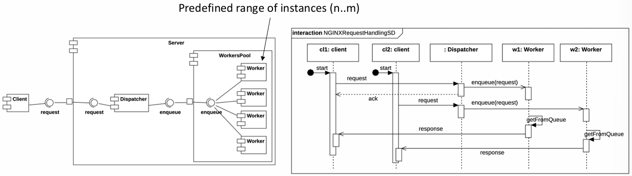
To address the limitations of the forking model, many modern web servers, such as NGINX, use a worker pooling approach. This design centers on a fixed number of worker threads or processes that handle incoming requests, ensuring the system remains efficient under high loads.
In the worker pooling model, the server creates a limited number of worker processes or threads when it starts up. Each worker is equipped with a queue to manage incoming requests, allowing the system to balance load without overloading resources.
Advantages of Worker Pooling
Resource Control: With a fixed number of workers, the server does not create additional processes on the fly, preventing resource exhaustion and improving predictability.
Efficient Queue Management: Each worker has a queue that holds incoming requests. If a queue is full, the dispatcher can either drop incoming requests or route them based on predefined policies, maintaining performance stability.
High Scalability: Since the server does not need to spawn a new process for each request, it can handle higher traffic levels more efficiently.
The worker pooling model introduces a new architectural tactic to enhance control over system attributes, particularly scalability and performance. However, it also involves quality attribute trade-offs. For instance, while this model optimizes performance and scalability, it may reduce availability in some cases. If all worker queues are full, the server may drop incoming requests rather than overloading the system, prioritizing stability over availability.
Three-Tier Architecture
The three-tier architecture is a common design pattern in software systems that separates different aspects of the application into three distinct layers: the presentation layer, the logic layer, and the data layer. This separation improves modularity, scalability, and maintainability.
In this example:
Tier 1 (Client): The client layer interacts with the logic layer (Tier 2). It can be a user interface or an external application that sends requests to the backend.
Tier 2 (Data warehouse Logic): This tier contains the logic and processing mechanisms of the system. It processes the client’s requests, often performing operations like aggregating, transforming, or filtering data. The logic is connected to the data layer (Tier 3), where it accesses and stores data.
Tier 3 (Data): This tier holds the actual data. It can be a database, file system, or external data producers providing raw data that is used in the business logic.
In this scenario, Producer X and Producer Y are external data sources or systems that provide data used by the data warehouse logic layer.
When scaling from a three-tier architecture to an N-tier architecture, you can introduce additional layers to handle specific concerns, such as different components of the system (e.g., ordering system, product catalog) or separate databases for better modularity.
In this more complex example:
Tier 1 (Client): The client interacts with the ordering system (Tier 3). It could be a customer ordering groceries from the supermarket’s online store or a mobile app.
Tier 2 (Data Warehouse Logic): This tier holds the core logic that connects the ordering system to the underlying data sources, such as pricing, inventory, or sales history.
Tier 3 (Ordering System): The ordering system manages and processes customer orders, integrating with data sources for real-time product availability and pricing.
Tier 4 (Data): Multiple producers (Producer X and Producer Y) provide various datasets needed by the system. This could include suppliers or external systems providing product data, price updates, or inventory.
By introducing more tiers (N-tier architecture), the system can better scale, isolate concerns, and provide more flexibility in handling specific business processes. In this case, the introduction of a dedicated ordering system (Tier 3) ensures the ordering process is managed separately from data warehousing or product information.
The -tier architecture supports various business needs such as scalability, flexibility, and improved maintainability by isolating distinct functionalities across multiple tiers.
Event-Driven Architecture (EDA)
Event-driven architecture is a design pattern where components communicate by sending and receiving events, rather than through direct requests or synchronous calls. This architecture is particularly useful in distributed, decoupled systems where real-time data updates or notifications are essential.
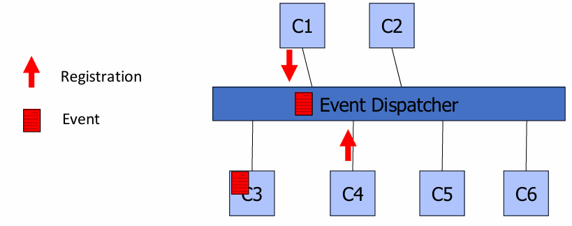
In this diagram:
Event Dispatcher (ED): The central component that receives and broadcasts events to all registered components.
Components (C1, C2, etc.): Each component can be a consumer or a producer of events.
Components register with the dispatcher to receive specific events or generate events.
The Event Dispatcher forwards these events to all subscribed components.
Key Characteristics:
No explicit naming of target components: Events are sent to all interested parties without the sender specifying a specific receiver.
Event-driven systems are often referred to as publish-subscribe systems, where:
Publish: An event is generated by a component, often representing a change or action (e.g., data update).
Subscribe: Components declare their interest in receiving specific types of events and act accordingly when such events are broadcast.
Different languages and protocols can support event definitions, including JSON, XML, and Protocol Buffers, depending on the requirements for interoperability, performance, and expressiveness.
Pros and Cons of Event-Driven Systems
Pros
Cons
Highly flexible: Components can be added, removed, or modified independently without reconfiguring the entire system.
Scalability: Managing numerous events or high traffic can be challenging.
Loose coupling: Sender and receiver do not depend on each other, enabling independent development and testing.
Event ordering: Event order is not guaranteed, which can introduce complications when events depend on sequence.
Responsiveness: Systems are often highly responsive to real-time data updates.
Complexity: Managing asynchronous events and error handling across distributed components can add complexity.
Additional characteristics of event-driven systems:
Asynchronous Messages: Events are asynchronous, allowing the sender to “send and forget” without waiting for the receiver to process it.
Reactive Computation: Processing occurs in response to incoming events, creating a responsive system that adapts in real-time.
Receiver-Determined Destination: The receiver decides which events to handle, making location and identity abstract for the sender.
Loose Coupling: Components can be added or removed with minimal impact on the overall system.
Flexible Communication Modes: Event-driven architecture supports various communication modes, including:
One-to-Many: One event is broadcast to multiple components.
Many-to-One: Multiple components generate events that one component receives and processes.
Many-to-Many: Multiple producers and consumers interact through shared events, enhancing flexibility and scalability.
Kafka’s Data Flow Architecture
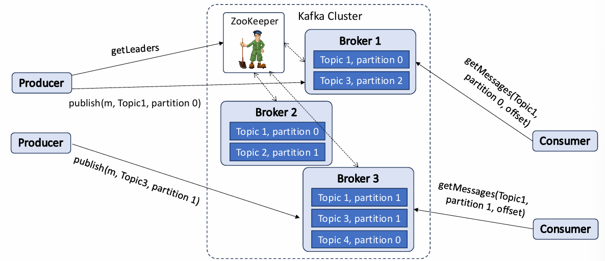
Apache Kafka is a distributed streaming platform that enables applications to produce, consume, and process streams of records in real time. It is widely used in event-driven architectures due to its robust support for both storing and transferring data streams in a scalable and fault-tolerant manner. At its core, Kafka provides a set of tools and abstractions to define and manage event producers and consumers, creating a resilient pipeline that efficiently transfers events from producers to consumers with minimal latency. Kafka operates on a distributed, scalable, and fault-tolerant infrastructure, making it a reliable choice for handling large volumes of data across various types of systems and applications.
In Kafka, producers are the components responsible for generating events and sending them to the Kafka cluster, while consumers are entities that read and process these events. Kafka brokers, which are the nodes within the Kafka cluster, serve as intermediaries that store, organize, and distribute events across consumers. Kafka is designed to be resilient and scalable; events are stored reliably across multiple brokers and can be processed by consumers as they arrive in real time or retrieved later. Kafka organizes events into topics, which represent logical channels for specific types of messages. Each topic can have multiple partitions, allowing messages within a topic to be distributed across brokers.
Each partition functions as an independent sequence of messages and can be replicated across multiple brokers to ensure data availability and fault tolerance. This replication strategy enhances reliability, as each partition has a designated leader broker responsible for handling all read and write requests, while other brokers act as followers. Producers send messages to these leader brokers, which batch them for efficiency before writing to the respective partitions. This batching process improves throughput by consolidating messages before sending them across the network.
Consumers, on the other hand, use a pull-based model to fetch messages from brokers. They specify an offset within each partition to mark their progress, enabling them to pick up messages from a particular point in the stream. Kafka’s design allows consumers to re-read messages within a configurable retention period, providing flexibility for applications that require reprocessing or failover mechanisms.
Reliability and Consistency through Message Delivery Semantics
Kafka’s message delivery semantics offer various levels of reliability, balancing performance and consistency based on application needs:
At-most-once semantics ensure that each message is delivered to the consumer no more than once. In this mode, a message’s offset is updated before processing, so if the consumer crashes, those messages are not reprocessed. This approach is efficient but risks data loss if a failure occurs after the offset is updated but before the message is processed.
At-least-once semantics provide higher reliability, ensuring that every message is processed at least once. Here, offsets are updated only after message processing is completed. In the case of a consumer failure, Kafka will reprocess messages from the last recorded offset, which may lead to duplicate processing but avoids message loss.
Exactly-once semantics provide the highest level of consistency. By coordinating offset management and message processing within a transactional context, Kafka enables precisely once delivery even in the face of failures. This option, while ensuring reliability, can introduce latency due to the additional transactional overhead required to manage and synchronize replicas.
Kafka’s Architecture and Operational Features
Kafka’s distributed architecture supports scalability by allowing the creation of multiple partitions within a topic, which are distributed across multiple brokers. This partitioning enables Kafka to handle enormous data volumes, as producers and consumers can operate in parallel across different partitions. Kafka clusters, which may consist of up to thousands of brokers, can manage trillions of messages daily, offering exceptional throughput and operational scale. Furthermore, Kafka’s built-in partition replication ensures fault tolerance. Replicated partitions provide redundancy, enabling Kafka to continue operating seamlessly even if individual brokers fail.
Kafka also relies on ZooKeeper to monitor the health and stability of the cluster. ZooKeeper maintains a record of broker activity through heartbeats sent by each broker. If a broker fails, ZooKeeper elects a new leader for any partitions that the failing broker was managing. ZooKeeper’s coordination and leadership election mechanisms enable Kafka to handle broker failures without service disruption, as leadership for partitions is reassigned dynamically.
Kafka brokers use a combination of commit logs and replication to ensure that messages are consistently and durably stored. When a producer sends a message, the leader broker commits it to the appropriate partition and replicates it to the follower brokers. In the event of a broker failure, Kafka’s replication mechanism guarantees that messages are retained across multiple brokers, minimizing the risk of data loss. Additionally, Kafka brokers have mechanisms to detect and eliminate duplicate messages, ensuring that even if a producer resends a message due to a failure, the system identifies and removes duplicates if transactional guarantees are required.
Scalability and Fault Tolerance in Kafka Clusters
Kafka’s architecture emphasizes both horizontal scalability and fault tolerance. By partitioning data and distributing these partitions across brokers, Kafka achieves a high level of throughput, as it can process multiple partitions concurrently across the cluster. Kafka’s architecture allows for elastic scalability, where brokers and partitions can be added to the cluster as needed without interrupting ongoing data flows. The replication of partitions across brokers is a key tactic for ensuring fault tolerance, as each partition has a leader and multiple followers, which can take over in case of leader failure.