Files and Filesystems
Disks can be seen by an OS as a collection of data blocks that can be read or written independently. To allow the ordering/management among them, each block is characterized by a unique numerical address called Logical Block Address (LBA). Typically, the OS groups blocks into clusters to simplify the access to the disk. Clusters are the minimal unit that an OS can read from or write to a disk. Typical cluster sizes range from 1 disk sector (512 bytes) to 128 sectors (64 KB).
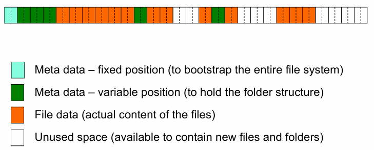
Any cluster contains two elements: the actual file data and the metadata. The metadata is used by the OS to keep track of the file’s location on the disk. Inside it, we can fine the name of the file, the directory structures and symbolic links, the size and the file type, when it was created, last modified, and last accessed. It contains also security information, such as the owner and the permissions associated with the file.
The disk can thus contain several type of clusters:
In order to read a file, the OS must first locate the file’s metadata to locate its block, the access to the pointed block and read its content. On the other hand, for writing a file, the OS must first access the metadata to locate free space where to write the file, then write the file’s content and update the metadata.
Since the filesystem can only access to clusters, the real occupation of space on a disk for a file is always a multiple of the cluster size. Given:
: the size of the file in bytes : the cluster size in bytes : the actual size of the file on the disk in bytes
we have that the actual size of the file on the disk is given by the formula:
and the quantity
Example
Given a file of 27 bytes with a cluster size of 8 bytes, the actual size of the file on the disk is
bytes. The wasted space is bytes.
Deleting a file require only to update the metadata, marking the cluster as free, by saying that the blocks where the file was stored are no longer in use by the OS. The actual data is not deleted, but it is no longer accessible by the OS. The space occupied by the file is then available for new files.
| Delete a file | Read a file | Remove a file | |
|---|---|---|---|
| Number of operations | 1 | 2 | 3 |
As the life of the disk evolves, there might not be enough space to store a file in a contiguous way. In this case, the file is split into smaller chunks that are inserted into the free clusters spread over the disk. The effect of splitting a file into non-contiguous clusters is called external fragmentation.
HDD
A hard disk drive (HDD) is a data storage using rotating disks (platters) coated with magnetic material. Data is read in a random-access manner, meaning that individual blocks of data can be stored or retrieved in any order rather than sequentially. An HDD consists of one or more rigid (“hard”) rotating disks (platters) with magnetic heads arranged on a moving actuator arm to read and write data to the surfaces. Externally, hard drives expose a large number of sectors (blocks), typically 512 or 4096 bytes each. Individual sector writes are atomic operations, while multiple sectors writes may be interrupted (turn write), only when only part of a multi-sector update are written successfully to the disk.
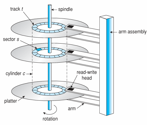
Drive geometry exposes sectors arranged in concentric circles (tracks) and sectors on each track. A cylinder is the set of all tracks with the same track number on all platters. A disk can be composed by multiple platters, each with two surfaces.
The motor drive spins the platters at a constant speed, typically 5400, 7200, 10000, or 15000 RPM. The actuator arm moves the heads to the desired track, and the heads read or write data as the platters spin. The time to move the heads to the desired track is called seek time
Typical interfaces for HDDs are:
- ST-506 (1980), ATA (1994), IDE (1994), SATA (2003): these interfaces are ancient standards for connecting HDDs to a computer. The commands (
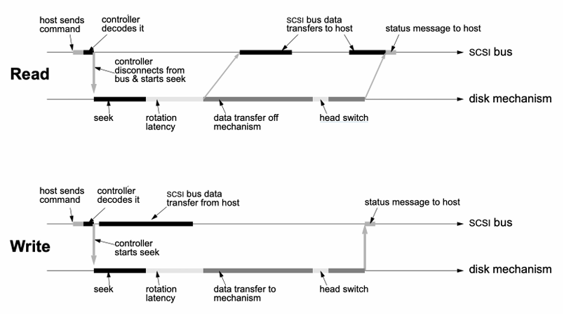
read/write) and addresses in cylinder/head/sector format placed in device registers are sent to the device. - SCSI (Small Computer System Interface, 1986): is a packet-based interface (like TCP/IP) where the device translates the LBA to an internal format (cylinder/head/sector) and sends the command to the device. This interface is device-independent and works for many different devices (USB drives, CD/DVD, Firewire, etc.). The iSCSI is a variant of SCSI that works over the network.
Delays
Definitions
In an HDD, there are four main types of delays:
- Rotational delay
: the time to rotate the desired sector to the read head. This is related to the rotational speed of the disk and the position of the head. - Seek time
: the time to move the head to the desired track. This is related to the speed of the actuator arm. - Transfer time
: the time to read or write the data from the disk. This is related to the speed of the disk and the interface. - Controller overhead
: the time to process the request and send it to the disk.
Rotational delay
The rotational delay is the time to rotate the desired sector to the read head. A full rotation delay is the time to rotate the disk once, which is called the rotational period. The rotational period is:
where
Seek time
The seek time
- acceleration: the time to accelerate the head to the desired speed
- coasting: the time to move the head at the desired constant speed
- deceleration: the time to decelerate the head to stop at the desired track
- settling: the time to wait for the head to stop moving
The seek time modelling consider a linear relationship between the distance to move and the time to move. The average seek time is the time to move the head to the middle of the disk:
where
Transfer time and controller overhead
The transfer time
The controller overhead
Definition
The transfer time (or service time) is given by the formula:
where
is the time to process the request and send it to the disk.
If there is a queue of requests, the time to wait for the disk to complete the operation is called the queue time. The queue time depends on the queue length, the resource utilization, mean and variance of the disk service time, and the scheduling algorithm.
Example
Given a disk with 10000 RPM, 6ms of mean seek time and 0.2ms of controller overhead, if we want to read/write a sector of 512 bytes at a transfer rate of 50 MB/s:
- the mean latency is:
- the mean transfer time is:
- the mean I/O service time is:
The previous service times considers only the very pessimistic case where sectors are fragmented on the disk in worst possible way. In case of very small files (each file is contained in a single block) or the disk is very fragmented (each block is in a different place), the seek time and the rotational delay are the dominant factors. In many circumstances, this is not the case, because files are larger than a single block and are stored in contiguous blocks. We can measure the data locality of a disk as the percentage of blocks that do not need seek or rotational latency to be found.
where
Example
Taking the previous example, if the data locality is 75%, seek and rotational delay are 25% of the time, and the average I/O service time is
so the mean time on one I/O operation is
Caching
To reduce the I/O time, many disks incorporate a small amount caches (track buffer), usually 8 to 32 MB. During the reading process, read caching reduces the read delays due to seeking and rotational latency. For the writing process, disk may perform two types of write caching:
- Write-back caching: the disk controller acknowledges the write operation as soon as the data is stored in the cache. The data is then written to the disk when the disk is idle. This technique is faster, but it may lose data in case of power failure.
- Write-through caching: the disk controller acknowledges the write operation only when the data is stored in the cache and on the disk. This technique is slower, but it is safer.
Today, some disk include flash memory for persistent storage, called hybrid drives. The flash memory is used as a cache for the most frequently accessed data, reducing the seek and rotational delays.
Disk scheduling
Caching helps to improve disk performance, but it can’t make up for poor random access times. The key idea to solve this problem is, if there are a queue of requests to the disk, they can be reordered to improve the disk performance. The estimation of the request length is feasible knowing the position on the disk of the data to read/write. The main disk scheduling algorithms are:
- First-Come-First-Served (FCFS): the requests are served in the order they arrive. This is the simplest algorithm, but it may lead to the head of the line blocking problem, where a request at the beginning of the queue prevents other requests from being served.
- Shortest Seek Time First (SSTF): the request with the shortest seek time is served first. This algorithm is optimal in terms of seek time, but it may lead to starvation of requests that are far from the disk head.
- SCAN: the disk head moves from the innermost to the outermost track, serving all requests in between. When the head reaches the outermost track, it moves back to the innermost track, serving all requests in between. This algorithm is also called Elevator.
- C-SCAN: like SCAN, but the head moves only in one direction. When the head reaches the outermost track, it moves back to the innermost track without serving any requests in between.
- C-LOOK: like SCAN, but the head moves only in one direction. When the head reaches the outermost track, it moves back to the innermost track without serving any requests in between. This algorithm is more efficient than C-SCAN.
Example
Starting from a data placed on the disk, the disk head is at track 53 and the disk is rotating clockwise. The disk has 200 tracks and the disk head moves at 1 track per millisecond. The disk has 10 requests to serve, placed at tracks 98, 183, 37, 122, 14, 124, 65, 67, 89, 170. The order of the requests served by the disk scheduling algorithms are:
- FCFS: 98, 183, 37, 122, 14, 124, 65, 67, 89, 170
- SSTF: 65, 67, 37, 14, 89, 98, 122, 124, 170, 183
- SCAN: 65, 67, 37, 14, 89, 98, 122, 124, 170, 183
- C-SCAN: 65, 67, 89, 98, 122, 124, 170, 183, 14, 37
- C-LOOK: 65, 67, 89, 98, 122, 124, 170, 183, 14, 37
The disk scheduling algorithms could me implemented in different ways:
- OS-level: the OS schedules the disk requests by reordering the requests by LBA, but it cannot take into account the disk rotation delay and the seek time
- Disk-level: the disk knows the exact position of the head and the disk, so it can possible to implement advanced algorithms, but requires a more complex disk controller and a more complex disk interface
- Disk-command-queue level: a component available in all modern HDDs, where a disk can stores pending requests; so, the disk can reorder the requests in the queue to optimize the disk performance and reduce the Seek time
- Joint OS-disk scheduling: the OS and the disk can cooperate to optimize the disk performance, but there might be some unexpected interactions between the two components that can lead to performance degradation