The main objective of cache memory is to enhance the performance of a computer’s memory system. It does this by creating the illusion of a large, fast memory, enabling the processor to access data quickly. Cache memory provides high-frequency data access to the processor, which ultimately boosts overall system performance.
Memory Hierarchy Design
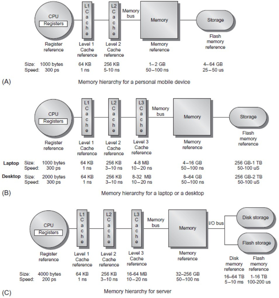
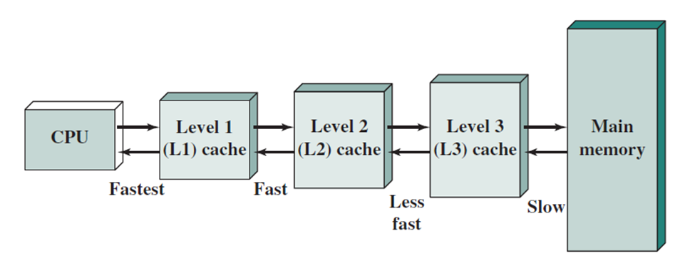
The design of the memory hierarchy becomes increasingly significant with the rise of multi-core processors. As the number of cores increases, so does the total peak bandwidth, necessitating the use of multi-port, pipelined caches. In modern systems, each core typically has two levels of cache, with a shared third-level cache on the chip. Effective memory hierarchy design must take into account the principle of locality of reference, which refers to the patterns in which data is accessed. Locality of reference can be broken down into two key types: temporal locality and spatial locality.
Definition
- Temporal locality refers to the tendency of recently accessed data to be accessed again in the near future. For example, instructions and data used in loops are often reused quickly.
- Spatial locality refers to the pattern where, once a particular data element is accessed, nearby data elements are likely to be accessed soon after. This is commonly observed in cases such as sequential instruction execution or accessing elements of arrays and matrices.
In a typical memory hierarchy, multiple levels of memory exist, with the upper levels (like cache) being smaller, faster, and more expensive than the lower levels (such as main memory). This structure enables the system to access the most frequently used data quickly, while still allowing access to larger volumes of data through slower memory levels.
Caches
Definition
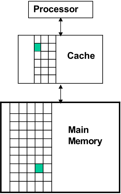
Cache memories are small, high-speed storage areas designed to hold copies of data from frequently accessed locations in main memory. They leverage both temporal and spatial locality by retaining recently accessed data (temporal locality) and by fetching data blocks surrounding recently accessed memory locations (spatial locality). The smallest unit of data that can be stored in the cache is a block (or cache line), which is a fixed-size chunk of memory.
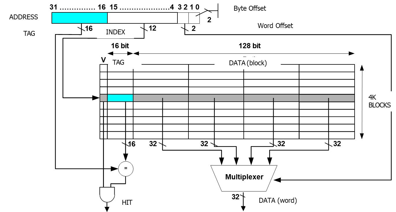
To optimize spatial locality, the cache block size is often chosen to be a multiple of the word size in memory, ensuring that entire chunks of data are transferred at once. The number of blocks in a cache can be calculated using the formula:
For example, a cache with a size of 64KB and a block size of 128 bits (16 bytes) would contain 4,096 blocks.
When data is requested from the cache, two possible outcomes occur: a cache hit or a cache miss:
- A cache hit happens when the requested data is found in one of the cache blocks.
- A cache miss occurs when the data is not present in the cache, necessitating access to the next level of memory, typically the main memory.
This process introduces a delay, as the CPU must stall while the data is fetched from the lower memory level, written into the cache, and the access is retried.
Cache Performance Metrics
Key performance metrics for caches include hit rate, hit time, miss rate, and miss penalty.
Definitions for cache hits
- Hit: data found in a block of the upper level
- Hit Rate: Number of memory accesses that find the data in the upper level with respect to the total number of memory accesses
- Hit Time: time to access the data in the upper level of the hierarchy, including the time needed to decide if the attempt of access will result in a hit or miss
Definitions for cache misses
- Miss: the data must be taken from the lower level
- Miss Rate: number of memory accesses not finding the data in the upper level with respect to the total number of memory accesses
- Miss Time: time needed to access the lower level and to replace the block in the upper level

The average memory access time (AMAT) is a crucial metric that quantifies the impact of cache performance on overall system performance. It can be calculated as:
Where the Miss Penalty refers to the additional time required to access data from the lower memory level.
Improving cache performance generally involves three strategies:
- Reducing the hit time.
- Minimizing the miss rate.
- Reducing the miss penalty.
Additionally, using a unified cache (as opposed to separate instruction and data caches) can improve performance. A unified cache serves both data and instructions, whereas in a Harvard architecture with separate caches, the average memory access time is computed as a weighted sum of the times for instruction and data cache accesses:
Cache Structure
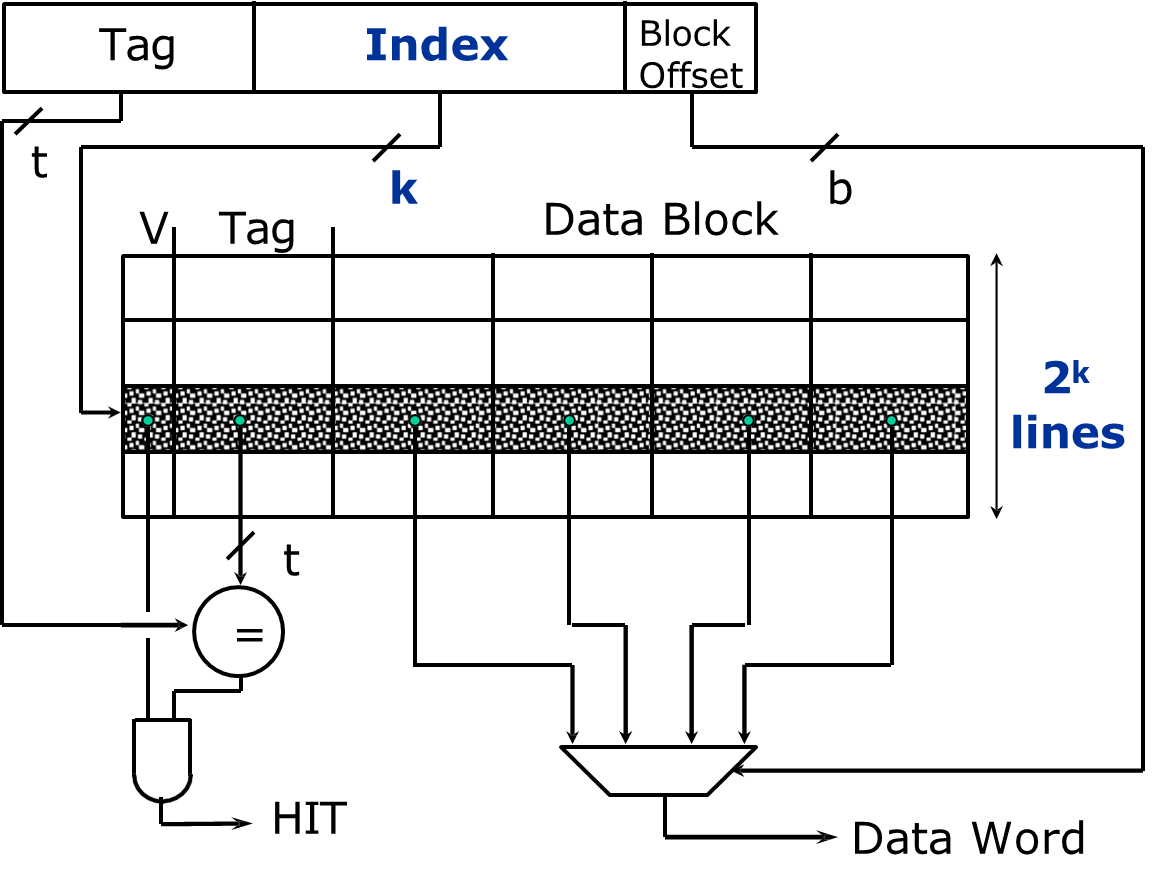
Each entry, or cache line, in a cache consists of three essential components:
- Valid bit: Indicates whether the data in the cache line is valid or invalid. At system startup, all cache lines are marked invalid until data is written into them.
- Cache Tag(s): These store the unique identifiers that correspond to the memory addresses from which the cache data is fetched. This helps in determining which block of memory is currently stored in the cache.
- Cache Data: This stores the actual data or the block of memory that is cached for faster access.
Block Placement
The problem of block placement in cache memory refers to how memory addresses are mapped to cache addresses. The way memory blocks are assigned to cache locations depends on the specific cache structure used. Different cache structures offer varying levels of flexibility in where a memory block can be placed, and each structure has its own advantages and disadvantages in terms of performance and complexity.
The main types of block placement strategies are:
- Direct Mapped Cache: Each memory block corresponds to exactly one cache block.
- Fully Associative Cache: A memory block can be placed in any cache location.
- n-way Set Associative Cache: The memory block can be placed in any block within a set, with each set containing a fixed number of blocks.
Summary
Block Placement Type Description Advantages Disadvantages Direct Mapped Cache Each memory block maps to exactly one cache block. Simple and fast to implement. High conflict miss rate if multiple blocks map to the same cache location. Fully Associative Cache A memory block can be placed in any cache location. Maximum flexibility, minimizes conflict misses. Complex hardware required for searching all cache lines, leading to longer access times. n-way Set Associative Cache A memory block can be placed in any block within a specific set. Balances simplicity and flexibility, reduces conflict misses compared to direct mapping. More complex than direct mapping, higher cost and access time than direct-mapped caches.
Direct Mapped Cache
In a direct-mapped cache, the mapping between memory blocks and cache blocks is simple and deterministic. For a given memory address, the corresponding cache address is determined by taking the modulus of the block address with respect to the total number of cache blocks. This mapping ensures that each memory block corresponds to one and only one cache block. The formula to calculate the cache address for a block in a direct-mapped cache is:
This straightforward mapping reduces the complexity of cache management but may lead to higher cache miss rates if multiple memory locations map to the same cache block.
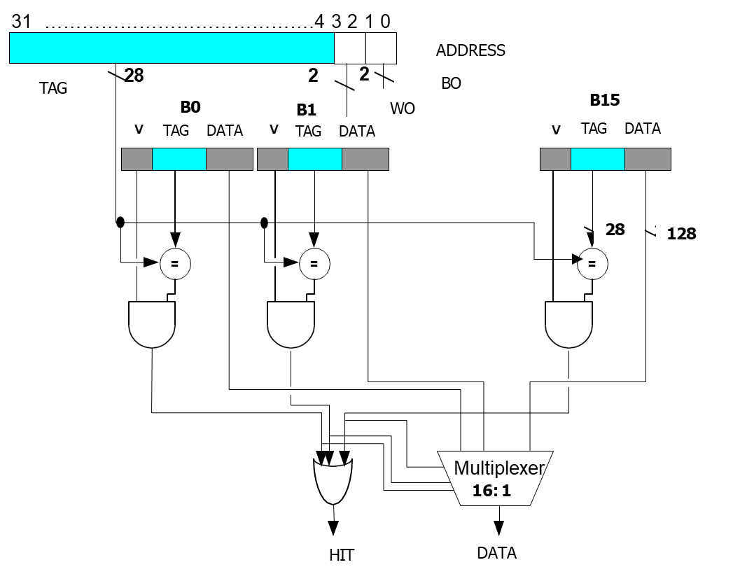
Fully Associative Cache
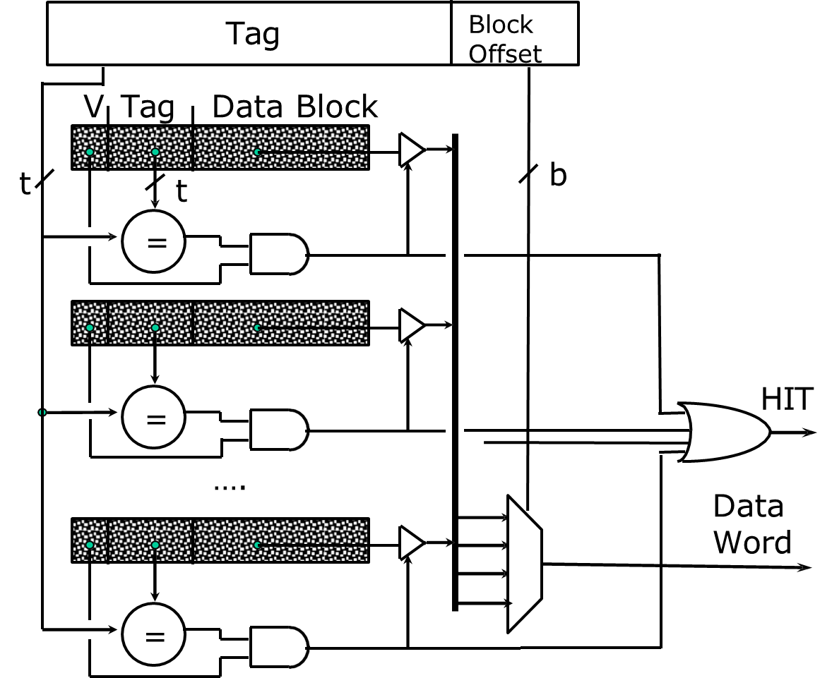
In a fully associative cache, the memory block can be placed in any cache location, allowing the cache to be more flexible in its management of memory blocks. Unlike the direct-mapped cache, there is no fixed relationship between memory locations and cache locations, and the block index in the memory address is absent. Instead, only the tag bits are used to identify whether a memory block is stored in the cache.
The absence of an index means that any memory block can potentially reside in any cache location, providing maximum flexibility. However, the increased flexibility requires more complex hardware mechanisms to search the entire cache for a potential match, which can lead to longer access times.
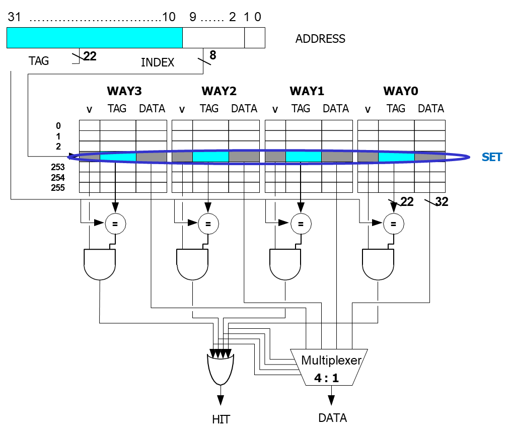
n-way Set Associative Cache
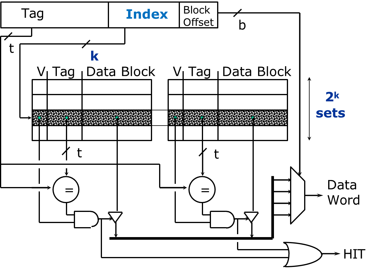
In an n-way set associative cache, the cache is divided into multiple sets, with each set containing
The memory address is divided into three parts: the tag, the set index, and the block offset. The cache location is determined by first selecting a set using the set index and then checking each block within that set to find the desired data.
The number of blocks in the cache is given by the formula:
The number of sets is given by:
The memory block can be placed in any of the
This structure strikes a balance between the simplicity of direct-mapped caches and the flexibility of fully associative caches. It reduces the risk of cache conflicts while avoiding the higher implementation cost of fully associative caches.
Increment of Associativity
One of the primary advantages of increasing the associativity of a cache is the reduction in the miss rate.
A higher associativity allows a memory block to be placed in any one of several cache locations, reducing the likelihood that multiple memory blocks will compete for the same cache location.
This flexibility generally leads to better cache performance, as fewer cache misses occur.
However, there are trade-offs to consider when increasing associativity. The main disadvantages include:
- Increased implementation cost: A more associative cache requires additional hardware to manage the multiple blocks per set and perform the necessary comparisons to find the appropriate cache block. This increases both the complexity of the cache controller and the physical size of the cache.
- Higher hit time: As associativity increases, it becomes more difficult to quickly find the correct cache block, which can increase the hit time (the time taken to retrieve data from the cache).
When choosing the appropriate level of associativity, system designers must weight the benefits of reducing the miss rate against the increased cost and complexity of the cache. As associativity increases, the number of index bits decreases, which expands the number of tag bits required for each cache line. This shift in the balance of bits can impact both the cache design and its performance.
Block Identification
Block identification refers to the process of determining whether a specific block of data is present in the cache. The method of identification varies based on the type of cache being used.
- In a direct-mapped cache, the cache address is determined by the index, which is calculated using the memory block number modulo the total number of cache blocks. Once the cache location is identified, the system compares the tag bits of the memory block with the tag bits stored in the cache. If they match, the valid bit is checked to ensure the cache block contains valid data.
- In a set-associative cache, the identification process is similar, but instead of searching the entire cache, we only search the set corresponding to the memory block. The set is identified by calculating the block number modulo the number of sets in the cache. Within the selected set, the system compares the tags of all blocks to the memory block’s tag, verifying the valid bit for a match.
- In a fully associative cache, the entire cache is treated as a single set, and there are no index or block offset bits. The system compares the tags of all blocks in the cache to the memory block’s tag and checks the valid bit. Since there is no set index, the comparison is exhaustive across all cache entries.
Block Replacement
Block replacement is a crucial aspect of cache management, especially in fully associative and set-associative caches. When a cache miss occurs, the system must decide which block in the cache to replace. In direct-mapped caches, since there is only one possible cache location for a memory block, no replacement strategy is needed.
In fully associative and set-associative caches, however, multiple blocks may map to the same set or cache location, requiring a strategy for selecting the block to evict. The most common block replacement strategies are:
- Random (or Pseudo-random): A block is selected for replacement at random, which is simple but may not always lead to optimal cache performance.
- LRU (Least Recently Used): The block that has not been accessed for the longest time is replaced. This strategy is more effective in reducing cache misses but requires more complex tracking mechanisms.
- FIFO (First In First Out): The oldest block in the cache is replaced. This approach is easier to implement but may not always be optimal for minimizing cache misses.
Each strategy has its own trade-offs in terms of hardware complexity and performance, and the choice of strategy often depends on the specific system requirements.
Write Policy
The write policy defines how data is written to the cache and the lower-level memory (such as main memory) when a write operation occurs. The two primary write policies are write-through and write-back.
| Advantages | Disadvantages | ||
|---|---|---|---|
| Write-Through | Data is written to both the cache and lower-level memory simultaneously. | Simplifies memory consistency, as cache and main memory always contain the same data. | Higher latency due to dual-write process, mitigated by using a write buffer. |
| Write-Back | Data is initially written only to the cache and written to lower-level memory when the cache block is replaced. | Reduces write traffic to main memory, improving overall system performance. | Potential issues with memory coherence, as cache and main memory may contain inconsistent data until the block is written back. |
-
In a write-through policy, data is written to both the cache and the lower-level memory simultaneously. This ensures that the memory hierarchy remains consistent, and the lower-level memory is always up-to-date. While write-through is simpler to implement and ensures that the memory is coherent, it can incur higher latency due to the need to write to both the cache and the main memory. To mitigate the impact of this dual-write process, a write buffer is often used to store data temporarily before it is written to main memory. This buffer helps avoid delays in CPU execution by allowing the processor to continue without waiting for the memory write to complete.
-
In a write-back policy, data is initially written only to the cache. The modified data is then written to the lower-level memory only when the cache block is replaced (on a cache miss). This approach is more efficient because it reduces the frequency of writes to the main memory, as multiple writes to the same block in the cache only result in a single write to memory when the block is evicted.
When using write-back, each cache block typically includes a dirty bit, which indicates whether the data in the cache block is different from the data in main memory. If the block is dirty, it will be written back to main memory when it is evicted.
Write-back reduces the write traffic to main memory, which can improve overall system performance, especially in systems where frequent writes occur. However, it introduces potential issues related to memory coherence, as the cache and main memory may contain inconsistent data until the block is written back.
Write Buffer

A write buffer is used to enhance performance in systems that employ a write-through policy (though it can also be used with write-back). It acts as an intermediate storage location for data that is being written from the cache to main memory. When the CPU writes to the cache, the data is also placed in the write buffer. The memory controller then writes the contents of the buffer to the lower-level memory asynchronously, allowing the processor to continue executing instructions without waiting for the memory write to complete.
One of the main challenges with write buffers is saturation, where the buffer becomes full, potentially causing the processor to stall until space becomes available. Efficient management of the write buffer is crucial for maintaining high performance in systems with heavy write operations.
Write Miss Options
When a write miss occurs, the system must decide whether to allocate a new cache line in the cache and write the data there. There are two main approaches for handling write misses:
- Write Allocate: In this approach, the system allocates a new cache line in the cache and writes the data to it. This often requires a “read miss” to fill the cache line with the necessary data before writing to it. Write Allocate is commonly used with write-back caches because it allows for multiple writes to the same block to be handled within the cache, reducing the number of writes to main memory.
- No Write Allocate: In this approach, the system directly writes the data to the lower-level memory (such as main memory) without allocating a new cache line. No Write Allocate is typically used with write-through caches, where the goal is to ensure that the data is written to memory immediately, without any attempt to hold it in the cache.
Both Write Allocate and No Write Allocate can be used with either write-through or write-back policies, depending on the desired system behavior. Generally, Write Allocate is favored in write-back caches because it minimizes main memory traffic by keeping the data in the cache, while No Write Allocate is preferred in write-through caches to avoid unnecessary cache allocation.
Miss Penalty Reduction: Second Level Cache
To reduce the miss penalty of the cache system, a second-level (L2) cache can be used to bridge the performance gap between the small, fast L1 cache and the slower main memory. This strategy is designed to increase the overall cache hit rate and decrease the time spent waiting for memory accesses.
- L1 Cache: Small and fast, optimized to match the cycle time of the CPU, but may not hold all the data required for program execution.
- L2 Cache: Larger and slower than L1, but still much faster than main memory. It serves as a backup for L1, reducing the penalty when L1 misses.
The Average Memory Access Time (AMAT) for a system with both L1 and L2 caches is given by the equation:
Where the Miss Penalty for L1 is defined as:
Thus, the overall AMAT for a system with two levels of cache can be rewritten as:
Where:
- Local miss rate refers to the miss rate in a specific cache (L1 or L2). For example, for L1, it’s the Miss Rate in L1, and for L2, it’s the Miss Rate in L2.
- Global miss rate refers to the fraction of memory accesses that eventually reach the main memory. For L1, the global miss rate is simply the Miss Rate in L1. For L2, the global miss rate is the combined effect of misses in both L1 and L2, which is calculated as:
The global miss rate is a crucial measure because it indicates how many accesses end up going all the way to main memory.
Types of Cache Misses
There are several types of cache misses, each caused by different factors. Understanding them helps in designing more efficient cache systems:
-
Compulsory (Cold Start) Misses:
- These occur when a block is accessed for the first time and is not in the cache.
- These misses are independent of cache size and can happen even in a cache with infinite capacity. For example, when a program first starts, there are many compulsory misses.
-
- These occur when the cache is too small to hold all the blocks needed for the program’s execution.
- As the cache is full and blocks are replaced, older blocks are evicted, causing the cache to miss when those evicted blocks are accessed again.
- The miss rate decreases as the cache size increases because more blocks can be held in the cache.
-
Conflict Misses:
- These happen when multiple memory blocks are mapped to the same cache location due to the block-placement strategy (e.g., direct-mapped or set-associative cache).
- Even though the cache may have space, a conflict miss can occur because the cache is unable to hold multiple blocks that map to the same index.
- Fully associative caches avoid conflict misses, but they require more hardware (increased area and power consumption).
-
Coherence Misses (in multi-core systems):
- These occur when a block is invalidated in one cache (due to updates in other caches or in main memory) and is then accessed in another cache.
- This type of miss is common in multi-core or multi-processor systems, where data consistency (cache coherence) between cores is crucial.
Memory Technology
The choice of memory technology influences both the speed and cost of the cache and main memory subsystems. Two primary types of memory used in modern systems are SRAM and DRAM.
-
SRAM (Static RAM):
- SRAM is used for cache memory because it is faster than DRAM and does not require refreshing, which makes it suitable for high-speed access.
- SRAM is built using six transistors per bit, making it more expensive and consuming more area compared to DRAM.
- It is ideal for use in the L1 and L2 caches because it can deliver low-latency access times.
-
DRAM (Dynamic RAM):
- DRAM is used for main memory due to its lower cost per bit and higher density compared to SRAM.
- DRAM is slower than SRAM and requires periodic refresh cycles to maintain data, making it unsuitable for use in cache memory.
- DRAM is built using a single transistor per bit and is more cost-effective for storing large amounts of data, such as in main memory.
The performance of the memory system is influenced by both latency (the time between a read request and the arrival of data) and bandwidth (the maximum amount of data that can be transferred per unit of time). SRAM is favored for its low latency, whereas DRAM is preferred for its larger storage capacity at a lower cost.