Stages of enterprise infrastructures
During the last 30 years, enterprise infrastructures have evolved and created different approach to deliver services to the users.
- Monolithic app: in this type of infrastructure, the network demands are minimal and the protocols are proprietary. This is a very simple infrastructure where the network is not a critical component and the requests are managed by a single server, so it’s a simple and cheap solution.
- Client server: in this type of infrastructure, the network demands are higher and the applications are walled within the enterprise. The TCP/IP protocol is used in combination with proprietary protocols to manage the network traffic.
- Web applications: in this type of infrastructure, the network demands are high and the applications are accessible from anywhere. The servers are broken into multiple units, each one with a web frontend, an application backend and a database, everything running on a virtual machine. The TCP/IP protocol is used to manage the network traffic and the services are accessible from the internet.
- Microservices: in this type of infrastructure, the network demands are very high and the applications are moved to the cloud. The servers are broken into microservices, each one running on a container and communicating with the others through a REST API. The network traffic is managed by a load balancer and the services are accessible from the internet.
While the first two approach are still used in many enterprises, the last two stages are becoming more and more popular due to the scalability and flexibility they offer. The microservices architecture is the most advanced and it’s used by many companies to deliver services to the users. While the performance of servers increases over time, the demand for inter-server bandwidth naturally increases as well. This is why the networking infrastructure is a critical component of a data center and it must be designed to support a very large number of servers and to provide a high level of performance. Networking has no straightforward horizontal scaling solution. Doubling the leaf bandwidth is easy: with twice as many servers, we’ll have twice as many network ports and thus twice as much bandwidth. But if we assume that every server needs to talk to every other server, we need to deal with bisection bandwidth.
Definition
The bisection bandwidth is the bandwidth across the narrowest line that equally divides the cluster into two parts. It characterizes network capacity since randomly communicating processors must send data across the “middle” of the network. If we assume that every server needs to talk to every other server, we need to double not just leaf bandwidth, but also the bisection bandwidth.
The key points to design a data center network are:
- Scalability: the network must be able to support a very large number of servers and to provide a high level of performance.
- Cost: the network must be cost-effective and must be designed to minimize the costs of the basic building blocks; this means that to reduce costs, the network must be designed to use the same type of equipment at all levels and to use old components as much as possible.
- Reliability: the network must be reliable and resilient to failures in order to be able to provide a high level of availability.
- Modularity: the network must be modular to reuse simple basic modules and to provide a high level of flexibility.
- Novel technologies: the network may exploit novel/proprietary technologies and protocols not compatible with legacy Internet.
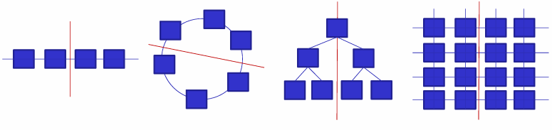
Data center networks can be classified into three main categories:
- Switch-centric architectures: use switches to perform packet forwarding.
- Switch-centric architectures: use servers with multiple Network Interface Cards (NICs) to act as switches in addition to performing other computational functions.
- Hybrid architectures: combine switches and servers for packet forwarding.
Switch-centric architectures
Definition
In a switch-centric architecture, switches are used to perform packet forwarding. They are designed to provide a high level of performance and scalability.
Switch-centric architectures are the most common type of data center networks. They use switches to perform packet forwarding. The switches are connected to the servers through access switches, which are connected to aggregation switches, which are connected to core switches. This architecture is very scalable and cost-effective, but it can be very expensive in large data centers since the upper layers require faster network equipment.
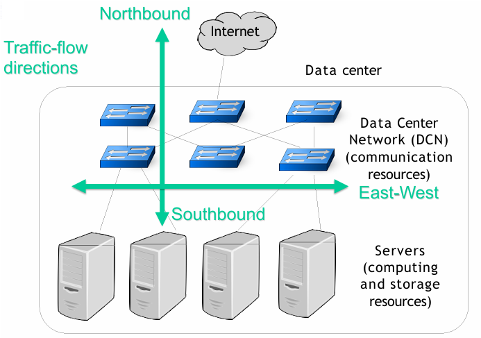
While the northbound traffic is the traffic that goes from the servers to the internet, there is another type of traffic called east-west traffic, which is the traffic that goes from one server to another server within the data center. This traffic is completely hidden to the user and it’s used for storage replication, VM migration, and network function virtualization, a process where data is processed through a sequence of VMs. The east-west traffic is usually larger than the north-south traffic and it’s a critical component of a data center network; about 76% of the traffic in a data center is east-west traffic in comparison to 17% of north-south traffic in a data center.
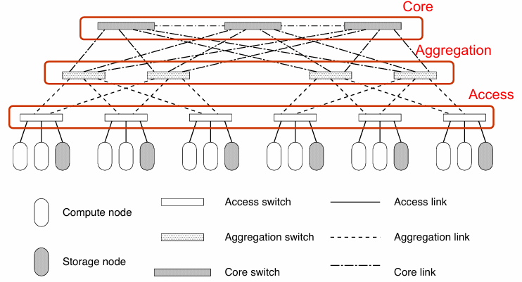
Three-Tier (or layer) “Classical” Network
This is the simplest type of data center network topology. The three-tier architecture configures the network in three different layers:
- Access layer: where the servers (compute and storage nodes) are connected to the network through access switches. Each access-level switch is connected to at least two aggregation-level switches.
- Aggregation layer: where the access switches are connected to the aggregation switches.
- Core layer: where the aggregation switches are connected to the core switches (gateways) to access the internet.
This architecture reflects the topology of the data center where each computational node inside the corridor is connected to TOR switches (access switches) and the TOR switches are connected to network aggregators (aggregation switches) placed at the end of the corridor. Each aggregator is connected to the core network equipment (core switches) through high-speed links.
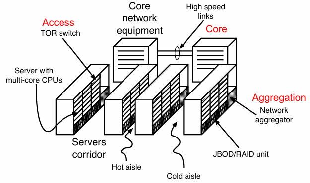
A standard 19-inch rack can house 42 EIA units (pizza box), this means that 40 server blades can be placed in a single rack, each one with a possible single subnet. The cabinet is connected to a single Top of Rack (ToR) switch.
- Without oversubscription (
, where is the number of servers and is the number of ports), the rack has 40 ports at 1 Gbit/s to the servers and 4 ports at 10 Gbit/s to the other switches. - With oversubscription (
), the rack has 40 ports at 1 Gbit/s to the servers and 1 port at 10 Gbit/s to the other switches.
Top of Rack (ToR) and End of Row (EoR)
ToR (Top-of-Rack) architecture is a type of data center network topology where all servers in a rack are connected to a ToR access switch within the same rack. The aggregation switches are stored in a dedicated racks or in shared racks with other ToR switches and servers. The number of cables is limited and the number of ports per switch is also limited, which reduces the costs of the network infrastructure. The downside of this architecture is the higher complexity for switch management.
EoR (End-of-Row) architecture is another type of data center network topology where the aggregation switches are positioned one per corridor, at the end of a line of racks. The servers in a rack are connected directly to the aggregation switch in another rack. The aggregation switches must have a larger number of ports and more complex cabling, longer cables are required, which increases the costs of the network infrastructure. A patch panel is used to connect the servers to the aggregation switch, which simplifies the switch management.
The bandwidth of a data center network can be increased by increasing the switches at the core and aggregation layers, and by using routing protocols such as Equal Cost Multiple Path (ECMP) that equally shares the traffic among different routes. The three-tier architecture is very simple, but it can be very expensive in large data centers since the upper layers require faster network equipment.
For example, 1 GB Ethernet is used at the access layer, 10 GB Ethernet is used at the aggregation layer, and 25 GB optical connections are used at the core layer.
The cost in terms of acquisition and energy consumption can be very high.
Leaf-Spine architectures
Leaf-Spine architectures
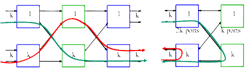
A Leaf-Spine architecture use a two-stage interconnection with leaf switches (ToR switches) and spine switches (aggregation switches). Each server has two interfaces connected to two ToR switches to provide fault-tolerance.

The spine-leaf topologies are borrowed from the telephone world and they are used in data center networks to provide a scalable and cost-effective solution. This is a non-folded Clos structure that uses leaf switches (ToR switches) and spine switches (aggregation switches) to provide a high level of performance and scalability.
Let
In a CLOS topology (where
If all the switches have an equal number of ports
Example of DCN design
- In the case of
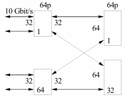
, we can connect 8 servers with 8 ports at 10 Gbit/s, which is equal to 80 Gbit/s. We can use 4 switches with 4 ports and 2 switches with 4 ports to build this network. - In the case of
, we can connect 2048 servers with 2048 ports at 10 Gbit/s, which is equal to 20.48 Tbit/s. We can use 64 switches with 64 ports and 32 switches with 64 ports to build this network.
The advantages of a Clos design in a data center network are:
- Use of homogeneous equipment, which reduces costs.
- Simple routing, with no need for complex routing protocols.
- The number of hops is the same for any pair of nodes, which reduces latency.
- Small blast radius in case of a failure, which increases reliability.
The disadvantage of a Clos design is that it cannot be scaled to multi-tier designs. One possible solution is to start with a two-tier network and add an additional row of switches and transform each spine-leaf group into a POD and add a super-spine tier.
Definition
This is a recursive leaf and spine topology where each leaf ha prectional ports. The network is built with
Fat Tree Network
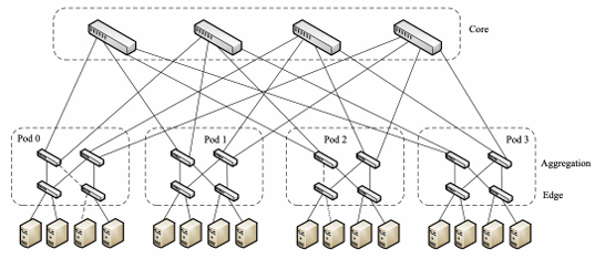
The fat tree network is a highly scalable and cost-efficient data center network architecture that aims to maximize bisection bandwidth. It can be built using commodity Gigabit Ethernet switches with the same number of ports. It is used by Microsoft and Amazon to provide a high level of performance and scalability.
At the edge layer, there are
Note the partial connectivity at switch level.
Server-centric architectures
Definition
Server-centric architectures use servers with multiple Network Interface Cards (NICs) to act as switches in addition to performing other computational functions.
There are four main types of server-centric architectures:
- CamCube: a server-centric architecture proposed for building container-sized data centers.
- DCell: a scalable and cost-efficient hybrid architecture that uses switches and servers for packet forwarding.
- BCube: a hybrid and cost-effective architecture that can scale up through recursion.
- MDCube: a server-centric architecture designed to reduce the number of cables in the interconnection of containers.
CamCube
CamCube is a server-centric architecture proposed for building container-sized data centers. It may reduce implementation and maintenance costs by using only servers to build the DCN. It uses a 3D-Torus topology to interconnect the servers directly and, as a torus-based architecture, it exploits network locality to increase communication efficiency.
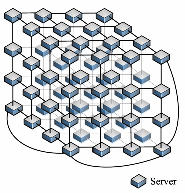
The drawbacks of CamCube are that it requires servers with multiple NICs to assemble a 3D Tours network, long paths, and high routing complexity.
DCell
DCell is a scalable and cost-efficient hybrid architecture that uses switches and servers for packet forwarding. It uses a recursive architecture with a basic building block called
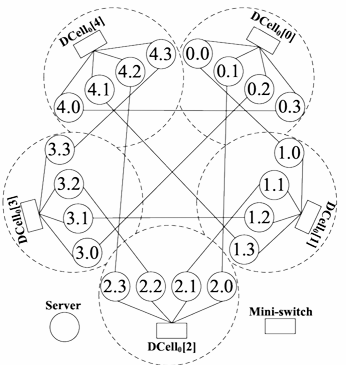
The drawbacks of DCell are long communication paths, many required NICs, and increased cabling costs.
BCube
BCube is a hybrid and cost-effective architecture that can scale up through recursion. It provides high bisection bandwidth and graceful degradation of throughput. It uses BCube as a building block, which can be used to construct larger BCubes. The BCube architecture is designed to provide a high level of performance and scalability.
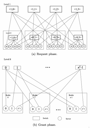
A
The drawbacks of BCube are the limited scalability and the high cost of cambling and NICs.
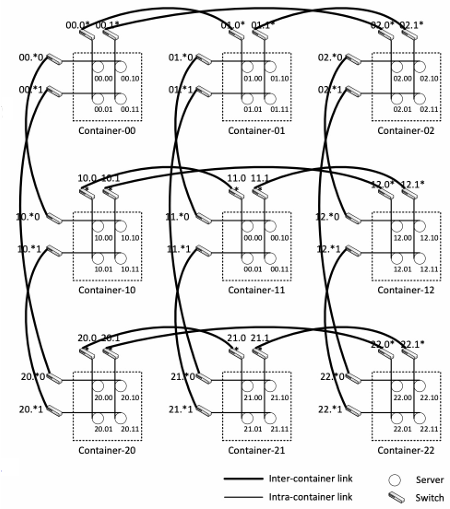
MDCube
It’s designed to reduce the number of cables in the interconnection of containers. Each container had an ID mapped to a multidimensional tuple and connected to the neighbor container with different tuple in one dimension. There are two types of links: intra-container links and high-speed inter-container links.
Addressing and routing in DCN
In a scenario with 100 thousand servers, with 32 VM each, there are
- Layer2: Single LAN limitations, routing as a tree topology, knowledge of the network discovered with broadcast messages.
- Layer3: Many VLAN and one subnet per VLAN, large number of DHCP servers, switches, and routers (including configurations).
Ad hoc solutions are needed, for example, VXLAN (Virtual Extensible LAN) that extends the VLAN addresses.
The success of WSC distributed storage system can be partially attributed to the evolution of the data center network fabrics (disk locality is no longer relevant in intra-data center computations). This observation enables dramatic simplification in the design of distributed disk-based storage system and utilization improvements, since any disk byte in a WSC facility can, in principle, be utilized by any task regardless of their relative locality.
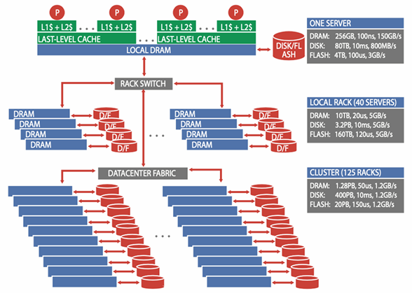
Example
We assume a system with 5,000 servers, each with 256 GB of DRAM, one 4 TB SSD, and eight 10 TB disk drives. Each group of 40 servers is connected through a 40-Gbps link to a rack-level switch (TOR). Each rack has an additional 10-Gbps uplink bandwidth per machine for connecting the rack to the cluster-level switch (AGGREGATION).
Network latency numbers assume a TCP/IP transport, and networking bandwidth values assume that each server is using its fair share of the available cluster-level bandwidth. For disks, typical commodity disk drive (SATA) latencies and transfer rates are considered.
A large application that requires servers in many racks to operate must deal effectively with large discrepancies in latency, bandwidth, and capacity. These discrepancies are much larger than those seen on a single machine, making it more difficult to program a WSC. A key challenge for architects of WSCs is to smooth out these discrepancies in a cost-efficient manner. A key challenge for software architects is to build SW infrastructure and services that hide this complexity.